POWER STEERING SYSTEM > TERMINALS OF ECU |
| CHECK POWER STEERING ECU ASSEMBLY |
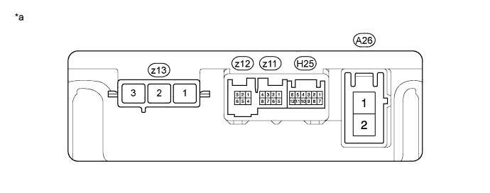
| *a | Component without harness connected (Power Steering ECU Assembly) | - | - |
| Terminal No. (Symbol) | Wiring Color | Terminal Description |
| z13-1 (V) | W | V phase motor output |
| z13-2 (U) | B | U phase motor output |
| z13-3 (W) | R | W phase motor output |
Measure the voltage and resistance according to the value(s) in the table below.
| Terminal No. (Symbol) | Wiring Color | Terminal Description | Condition | Specified Condition |
| A26-1 (PIG) - A26-2 (PGND) | W - W-B | Power source | Always | 9 to 16 V |
| A26-2 (PGND) - Body ground | W-B - Body ground | Power ground | Always | Below 1 Ω |
| H25-1 (CANH) - H25-7 (CANL) | R - W | CAN communication line | Power switch off | 54 to 69 Ω |
| H25-6 (IG) - A26-2 (PGND) | G - W-B | IG power source | Power switch on (IG) | 9 to 16 V |
| z12-1 (RZV) - A26-2 (PGND) | R - W-B | Rotation angle sensor excitation output signal | Power switch on (READY) Steering wheel turned | 0.68 to 4.42 V |
| z12-3 (RZG) - A26-2 (PGND) | B - W-B | Rotation angle sensor excitation circuit GND | Always | Below 1 Ω |
| z12-5 (RZCS) - A26-2 (PGND) | L - W-B | Rotation angle sensor COS aspect output signal | Power switch on (READY) Steering wheel turned | 0.68 to 4.42 V |
| z12-6 (RZSN) - A26-2 (PGND) | Y - W-B | Rotation angle sensor SIN aspect output signal | Power switch on (READY) Steering wheel turned | 0.68 to 4.42 V |
| z11-5 (TRQ1) - z11-8 (TRQG) | W - B | Torque sensor signal | Power switch on (READY) Steering wheel not being turned (without load) | 2.3 to 2.7 V |
| Power switch on (READY) Steering wheel turned being to right with vehicle stopped | 2.5 to 3.8 V | |||
| Power switch on (READY) Steering wheel being turned to left with vehicle stopped | 1.2 to 2.5 V | |||
| z11-6 (TRQV) - z11-8 (TRQG) | R - B | Torque sensor voltage source | Power switch on (IG) | 4.5 to 5.5 V |
| z11-7 (TRQ2) - z11-8 (TRQG) | Y - B | Torque sensor signal | Power switch on (READY) Steering wheel not being turned (without load) | 2.3 to 2.7 V |
| Power switch on (READY) Steering wheel being turned to right with vehicle stopped | 1.2 to 2.5 V | |||
| Power switch on (READY) Steering wheel being turned to left with vehicle stopped | 2.5 to 3.8 V | |||
| z11-8 (TRQG) - Body ground | B - Body ground | Torque sensor ground | Always | Below 1 Ω |
