SFI SYSTEM > Fuel Pump Control Circuit |
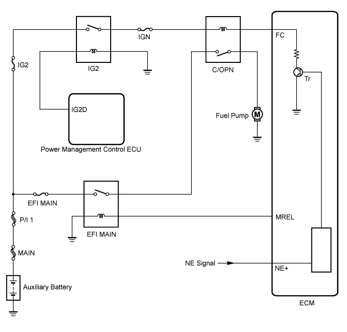
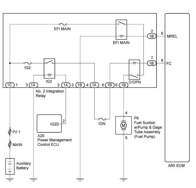
| 1.PERFORM ACTIVE TEST USING INTELLIGENT TESTER (CONTROL THE FUEL PUMP/SPEED) |
Connect the intelligent tester to the DLC3.
Turn the power switch on (IG).
Turn the tester on.
Enter the following menus: Powertrain / Engine and ECT / Active Test / Control the Fuel Pump/Speed.
Check whether the fuel pump operation sound occurs when performing the Active Test on the tester.
|
| ||||
| OK | ||
 | ||
| ||
| 2.INSPECT NO. 2 INTEGRATION RELAY (C/OPN RELAY) |
Inspect the No. 2 integration relay (C/OPN relay ) (Click here).
|
| ||||
| OK | |
 |
| 3.CHECK HARNESS AND CONNECTOR (NO. 2 INTEGRATION RELAY (C/OPN RELAY) - ECM) |
Disconnect the ECM connector.
Remove the No. 2 integration relay from the engine room relay block.
Disconnect the No. 2 integration relay connector.
Measure the resistance according to the value(s) in the table below.
| Tester Connection | Condition | Specified Condition |
| 1B-7 - A60-8 (FC) | Always | Below 1 Ω |
| 1B-7 or A60-8 (FC) - Body ground | Always | 10 kΩ or higher |
|
| ||||
| OK | |
|
| 4.CHECK HARNESS AND CONNECTOR (NO. 2 INTEGRATION RELAY (C/OPN RELAY - IG2 RELAY)) |
Remove the No. 2 integration relay from the engine room relay block.
Disconnect the No. 2 integration relay connector.
Measure the resistance according to the value(s) in the table below.
| Tester Connection | Condition | Specified Condition |
| 1A-4 - 1B-6 | Always | Below 1 Ω |
| 1A-4 or 1B-6 - Body ground | Always | 10 kΩ or higher |
|
| ||||
| OK | |
|
| 5.CHECK HARNESS AND CONNECTOR (NO. 2 INTEGRATION RELAY (C/OPN RELAY) - FUEL PUMP) |
Disconnect the fuel pump connector.
Remove the No. 2 integration relay from the engine room relay block.
Disconnect the No. 2 integration relay connector.
Measure the resistance according to the value(s) in the table below.
| Tester Connection | Condition | Specified Condition |
| 1B-8 - P9-4 | Always | Below 1 Ω |
| 1B-8 or P9-4 - Body ground | Always | 10 kΩ or higher |
|
| ||||
| OK | |
|
| 6.CHECK HARNESS AND CONNECTOR (FUEL PUMP - BODY GROUND) |
Disconnect the fuel pump connector.
Measure the resistance according to the value(s) in the table below.
| Tester Connection | Condition | Specified Condition |
| P9-5 - Body ground | Always | Below 1 Ω |
|
| ||||
| OK | |
|
| 7.INSPECT FUEL PUMP |
Inspect the fuel pump (Click here).
|
| ||||
| OK | |
|
| 8.CHECK ECM POWER SOURCE CIRCUIT |
Check the ECM power source circuit (Click here).
|
| ||||
| OK | ||
| ||
| ||


