SFI SYSTEM > ECM Power Source Circuit |
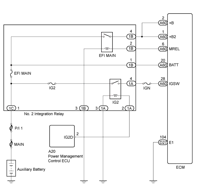
| 1.CHECK HARNESS AND CONNECTOR (ECM - BODY GROUND) |
Disconnect the ECM connector.
Measure the resistance according to the value(s) in the table below.
| Tester Connection | Condition | Specified Condition |
| D27-104 (E1) - Body ground | Always | Below 1 Ω |
|
| ||||
| OK | |
 |
| 2.INSPECT ECM (IGSW VOLTAGE) |
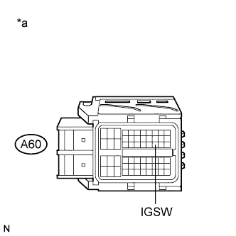 |
Disconnect the ECM connector.
Turn the power switch on (IG).
Measure the voltage according to the value(s) in the table below.
| Tester Connection | Switch Condition | Specified Condition |
| A60-28 (IGSW) - Body ground | Power switch on (IG) | 11 to 14 V |
| *a | Front view of wire harness connector (to ECM) |
|
| ||||
| OK | |
|
| 3.INSPECT NO. 2 INTEGRATION RELAY (EFI MAIN RELAY) |
Inspect the No. 2 integration relay (EFI MAIN relay) (Click here).
|
| ||||
| OK | |
|
| 4.CHECK HARNESS AND CONNECTOR (NO. 2 INTEGRATION RELAY (EFI MAIN RELAY) - ECM) |
Remove the No. 2 integration relay (EFI MAIN relay) from the engine room relay block.
Disconnect the No. 2 integration relay connector.
Disconnect the ECM connector.
Measure the resistance according to the value(s) in the table below.
| Tester Connection | Condition | Specified Condition |
| 1B-4 - A60-1 (+B2) | Always | Below 1 Ω |
| 1B-4 - A60-2 (+B) | Always | Below 1 Ω |
| 1B-2 - A60-6 (MREL) | Always | Below 1 Ω |
| 1B-4 or A60-1 (+B2) - Body ground | Always | 10 kΩ or higher |
| 1B-4 or A60-2 (+B) - Body ground | Always | 10 kΩ or higher |
| 1B-2 or A60-6 (MREL) - Body ground | Always | 10 kΩ or higher |
|
| ||||
| OK | |
|
| 5.CHECK HARNESS AND CONNECTOR (NO. 2 INTEGRATION RELAY (EFI MAIN RELAY) - AUXILIARY BATTERY) |
Remove the No. 2 integration relay (EFI MAIN relay) from the engine room relay block.
Disconnect the No. 2 integration relay connector.
Disconnect the negative (-) auxiliary battery terminal.
Disconnect the positive (+) auxiliary battery terminal.
Measure the resistance according to the value(s) in the table below.
| Tester Connection | Condition | Specified Condition |
| 1C-1 - Positive (+) auxiliary battery terminal | Always | Below 1 Ω |
| 1C-1 or Positive (+) auxiliary battery terminal - Body ground | Always | 10 kΩ or higher |
|
| ||||
| OK | |
|
| 6.CHECK HARNESS AND CONNECTOR (NO. 2 INTEGRATION RELAY (EFI MAIN RELAY) - BODY GROUND) |
Remove the No. 2 integration relay (EFI MAIN relay) from the engine room relay block.
Disconnect the No. 2 integration relay connector.
Measure the resistance according to the value(s) in the table below.
| Tester Connection | Condition | Specified Condition |
| 1B-3 - Body ground | Always | Below 1 Ω |
|
| ||||
| OK | ||
 | ||
| ||
| 7.INSPECT NO. 2 INTEGRATION RELAY (IG2 RELAY) |
Inspect the No. 2 integration relay (IG2 relay) (Click here).
|
| ||||
| OK | |
|
| 8.CHECK HARNESS AND CONNECTOR (NO. 2 INTEGRATION RELAY (IG2 RELAY) - ECM) |
Disconnect the ECM connector.
Remove the No. 2 integration relay (IG2 relay) from the engine room relay block.
Disconnect the No. 2 integration relay connector.
Measure the resistance according to the value(s) in the table below.
| Tester Connection | Condition | Specified Condition |
| 1A-4 - A60-28 (IGSW) | Always | Below 1 Ω |
| 1A-4 or A60-28 (IGSW) - Body ground | Always | 10 kΩ or higher |
|
| ||||
| OK | |
|
| 9.CHECK HARNESS AND CONNECTOR (NO. 2 INTEGRATION RELAY (IG2 RELAY) - AUXILIARY BATTERY) |
Remove the No. 2 integration relay (IG2 relay) from the engine room relay block.
Disconnect the No. 2 integration relay connector.
Disconnect the negative (-) auxiliary battery terminal.
Disconnect the positive (+) auxiliary battery terminal.
Measure the resistance according to the value(s) in the table below.
| Tester Connection | Condition | Specified Condition |
| 1C-1 - Positive (+) auxiliary battery terminal | Always | Below 1 Ω |
| 1C-1 or Positive (+) auxiliary battery terminal - Body ground | Always | 10 kΩ or higher |
|
| ||||
| OK | |
|
| 10.CHECK HARNESS AND CONNECTOR (NO. 2 INTEGRATION RELAY (IG2 RELAY) - BODY GROUND) |
Remove the No. 2 integration relay (IG2 relay) from the engine room relay block.
Disconnect the No. 2 integration relay connector.
Measure the resistance according to the value(s) in the table below.
| Tester Connection | Condition | Specified Condition |
| 1A-3 - Body ground | Always | Below 1 Ω |
|
| ||||
| OK | |
|
| 11.CHECK HARNESS AND CONNECTOR (POWER MANAGEMENT CONTROL ECU - INTEGRATION RELAY (IG2 RELAY)) |
Remove the No. 2 integration relay (IG2 relay) from the engine room relay block.
Disconnect the No. 2 integration relay connector.
Disconnect the power management control ECU connector.
Measure the resistance according to the value(s) in the table below.
| Tester Connection | Condition | Specified Condition |
| A20-2 (IG2D) - 1A-2 | Always | Below 1 Ω |
|
| ||||
| OK | ||
| ||
| ||


