POWER STEERING SYSTEM > EPS Warning Light Circuit |
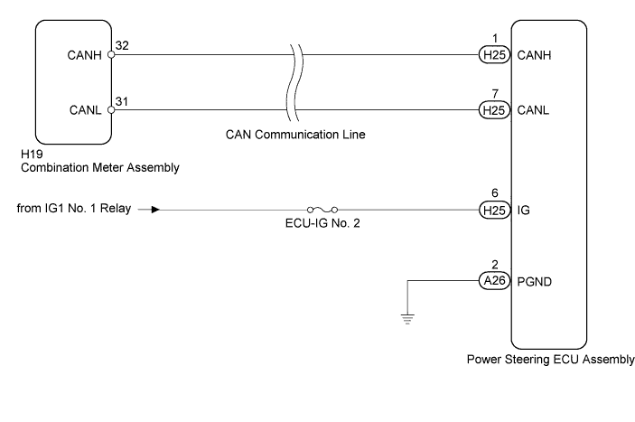
| 1.CHECK FOR DTC (CAN COMMUNICATION SYSTEM) |
Check for DTCs (Click here).
|
| ||||
| OK | |
 |
| 2.CHECK HARNESS AND CONNECTOR (POWER STEERING ECU ASSEMBLY - BODY GROUND) |
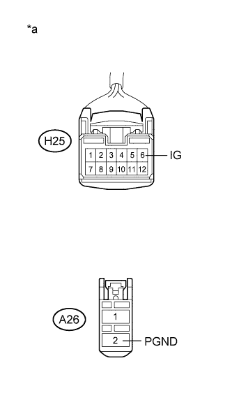 |
Disconnect the connectors from the power steering ECU assembly.
Measure the voltage according to the value(s) in the table below.
| Tester Connection | Condition | Specified Condition |
| H25-6 (IG) - A26-2 (PGND) | Power switch on (IG) | 9 to 16 V |
Measure the resistance according to the value(s) in the table below.
| Tester Connection | Condition | Specified Condition |
| A26-2 (PGND) - Body ground | Always | Below 1 Ω |
| *a | Front view of wire harness connector (to Power Steering ECU Assembly) |
|
| ||||
| OK | |
|
| 3.PERFORM ACTIVE TEST USING INTELLIGENT TESTER |
Turn the power switch off.
Connect the intelligent tester to the DLC3.
Turn the power switch on (IG).
Turn the intelligent tester on.
Enter the following menus: Body / Combination Meter / Active Test.
Perform the Active Test of the combination meter assembly using the intelligent tester.
| Tester Display | Test Part | Control Range | Diagnostic Note |
| Indicat. EPS | P/S warning light | OFF or ON | Confirm that the vehicle is stopped with the engine idling |
Check that the P/S warning light operates in accordance with the Active Test.
|
| ||||
| OK | ||
 | ||
| ||

