DTC C1552 PIG Power Supply Voltage Malfunction |
DTC C1554 Power Supply Relay Failure |
| DTC No. | DTC Detection Condition | Trouble Area |
| C1552 | PIG power source circuit malfunction inside ECU |
|
| C1554 | Power source relay circuit malfunction |
|
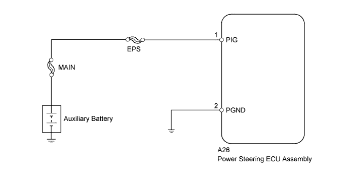
| 1.READ VALUE USING INTELLIGENT TESTER (PIG POWER SUPPLY) |
Turn the power switch off.
Connect the intelligent tester to the DLC3.
Turn the power switch on (READY).
Turn the intelligent tester on.
Enter the following menus: Chassis / EMPS / Data List.
Select the item "PIG Power Supply" in the Data List and read the value displayed on the intelligent tester.
| Tester Display | Measurement Item/Range | Normal Condition | Diagnostic Note |
| PIG Power Supply | PIG power supply/ Min.: 0 V Max.: 20.1531 V | 9 to 16 V | Power switch on (READY) and steering wheel being turned |
|
| ||||
| OK | ||
 | ||
| ||
| 2.CHECK HARNESS AND CONNECTOR (POWER STEERING ECU ASSEMBLY - AUXILIARY BATTERY AND BODY GROUND) |
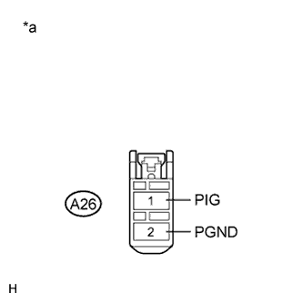 |
Disconnect the connector from the power steering ECU assembly.
Measure the voltage according to the value(s) in the table below.
| Tester Connection | Condition | Specified Condition |
| A26-1 (PIG) - Body ground | Always | 9 to 16 V |
Measure the resistance according to the value(s) in the table below.
| Tester Connection | Condition | Specified Condition |
| A26-2 (PGND) - Body ground | Always | Below 1 Ω |
| *a | Front view of wire harness connector (to Power Steering ECU Assembly) |
|
| ||||
| OK | ||
| ||
| ||


