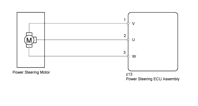
DTC C1522 Motor Circuit Malfunction |
DTC C1523 Motor Circuit Malfunction |
DTC C1524 Motor Circuit Malfunction |
DTC C1555 Motor Relay Welding Failure |
| DTC No. | DTC Detection Condition | Trouble Area |
| C1522 | Motor current sensor malfunction |
|
| C1523 | Excessively large current deviation | |
| C1524 | Short (or open) in motor circuit or abnormal voltage or current in motor circuit | |
| C1555 | Motor relay circuit malfunction |
| 1.READ VALUE USING INTELLIGENT TESTER (MOTOR VOLTAGE) |
Turn the power switch off.
Connect the intelligent tester to the DLC3.
Turn the power switch on (READY).
Turn the intelligent tester on.
Enter the following menus: Chassis / EMPS / Data List.
Select the items "Motor Terminal Volt (U)", "Motor Terminal Volt (V)" and "Motor Terminal Volt (W)" in the Data List and read the value displayed on the intelligent tester.
| Tester Display | Measurement Item/Range | Normal Condition | Diagnostic Note |
| Motor Terminal Volt (U) | Motor terminal voltage (U phase)/ Min.: 0 V Max.: 98 V | Value changes within 4 to 35 V range | Power switch on (READY) and steering wheel being turned |
| Motor Terminal Volt (V) | Motor terminal voltage (V phase)/ Min.: 0 V Max.: 98 V | Value changes within 4 to 35 V range | Power switch on (READY) and steering wheel being turned |
| Motor Terminal Volt (W) | Motor terminal voltage (W phase)/ Min.: 0 V Max.: 98 V | Value changes within 4 to 35 V range | Power switch on (READY) and steering wheel being turned |
| Condition | Proceed to |
| During steering operation, value changes within 4 to 35 V range | A |
| During steering operation, voltage is not generated | B |
|
| ||||
| A | ||
 | ||
| ||

