CAMSHAFT > INSTALLATION |
| 1. INSTALL NO. 1 CAMSHAFT BEARING |
Clean both surfaces of the bearings.
Install the 2 No. 1 camshaft bearings.
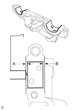 |
Using a vernier caliper, measure the distance between the bearing cap edge and the camshaft bearing edge.
| *1 | Vernier Caliper |
| 2. INSTALL NO. 2 CAMSHAFT BEARING |
Clean both surfaces of the bearings.
Install the 2 No. 2 camshaft bearings.
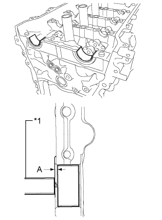 |
Using a vernier caliper, measure the distance between the bearing cap edge and the camshaft bearing edge.
| *1 | Vernier Caliper |
| 3. INSTALL NO. 2 CAMSHAFT |
Clean the camshaft journals.
Apply a light coat of engine oil to the camshaft journals, camshaft housings and bearing caps.
Install the No. 2 camshaft to the camshaft housing.
| 4. INSTALL CAMSHAFT |
Clean the camshaft journals.
Apply a light coat of engine oil to the camshaft journals, camshaft housings and bearing caps.
Install the camshaft to the camshaft housing.
| 5. INSTALL BEARING CAP |
Apply engine oil to the camshaft journals, camshaft housings and bearing caps.
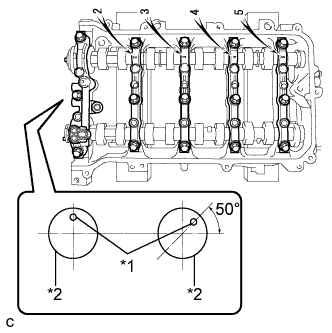 |
Make sure of the marks and numbers on the camshaft bearing caps and place them in each proper position and direction.
| *1 | Knock Pin |
| *2 | Camshaft |
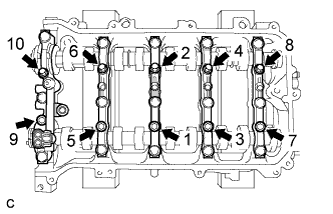 |
Tighten the 10 bolts in the order shown in the illustration.
| 6. INSTALL CAMSHAFT HOUSING SUB-ASSEMBLY |
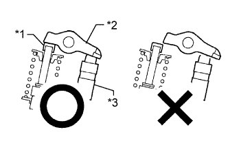 |
Check that the valve rocker arms are installed as shown in the illustration.
| *1 | Valve Stem Cap |
| *2 | Valve Rocker Arm |
| *3 | Valve Lash Adjuster |
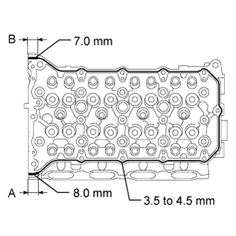 |
Apply seal packing in a continuous line as shown in the illustration.
| Area | Specified Condition |
| Continuous line | 3.5 to 4.5 mm (0.138 to 0.177 in.) |
| A | 8.0 mm (0.315 in.) |
| B | 7.0 mm (0.276 in.) |
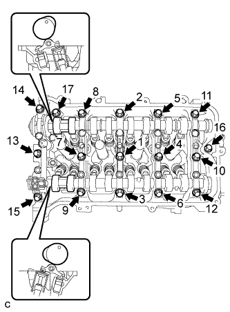 |
Set the camshaft and No. 2 camshaft as shown in the illustration.
Install the camshaft housing with the 17 bolts and tighten them in the order shown in the illustration.
| 7. INSTALL CAMSHAFT TIMING SPROCKET |
Tighten the flange bolt with the camshaft timing sprocket secured in place.
| 8. INSTALL CAMSHAFT TIMING GEAR ASSEMBLY |
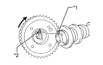 |
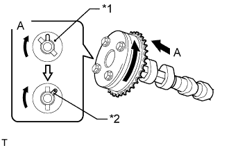
Put the camshaft timing gear and camshaft together with the straight pin and key groove misaligned as shown in the illustration.
| *1 | Straight Pin |
| *2 | Key Groove |
 |
Turn the camshaft timing gear as shown in the illustration while pushing it gently against the camshaft. Push further at the position where the pin fits into the groove.
| *1 | Straight Pin |
| *2 | Key Groove |
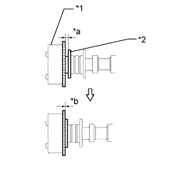 |
Check that there is no clearance between the camshaft timing gear and camshaft flange.
| *1 | Camshaft Timing Gear |
| *2 | Flange |
| *a | Clearance |
| *b | No Clearance |
Tighten the flange bolt with the camshaft timing gear secured in place.
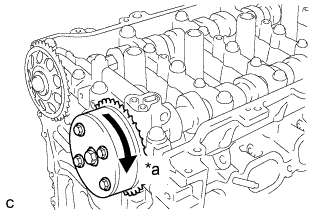 |
Check that the camshaft timing gear can move in the retard direction (clockwise) and lock it in the most retarded position.
| *a | Lock |
| 9. INSTALL NO. 1 CHAIN VIBRATION DAMPER |
Install the chain vibration damper with the 2 bolts.
| 10. SET NO. 1 CYLINDER TO TDC/COMPRESSION |
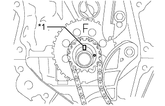 |
Temporarily install the crankshaft pulley bolt.
| *1 | Timing Gear Key |
Turn the crankshaft to position the timing gear key to the top.
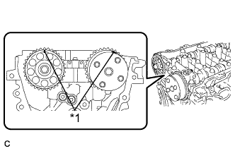 |
Check that the timing marks on the camshaft timing gear and camshaft timing sprocket are aligned as shown in the illustration.
| *1 | Timing Mark |
Remove the crankshaft pulley bolt.
| 11. INSTALL CHAIN SUB-ASSEMBLY |
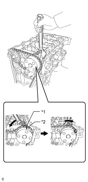 |
Align the mark plate (orange) with the timing mark as shown in the illustration and install the chain.
| *1 | Mark Plate (Orange) |
| *2 | Timing Mark |
Hold the hexagonal portion of the camshaft with a wrench and turn the camshaft timing gear counterclockwise to align the mark plate (orange) and timing mark, and then install the chain.
Hold the hexagonal portion of the camshaft with a wrench and turn the camshaft timing gear clockwise.
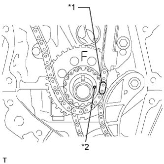 |
Align the mark plate (yellow) and timing mark and install the chain to the crankshaft timing gear.
| *1 | Mark Plate (Yellow) |
| *2 | Timing Mark |
| 12. CHECK NO. 1 CYLINDER TO TDC/COMPRESSION |
Check each timing mark at TDC/compression.
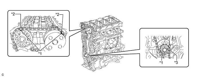
| *1 | Timing Mark | *2 | Mark Plate (Orange) |
| *3 | Mark Plate (Yellow) | - | - |
| 13. INSTALL NO. 2 CHAIN VIBRATION DAMPER |
Install the No. 2 chain vibration damper with the 2 bolts.
| 14. INSTALL CHAIN TENSIONER SLIPPER |
Install the chain tensioner slipper to the cylinder block.
| 15. INSTALL TIMING CHAIN COVER OIL SEAL |
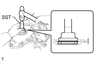 |
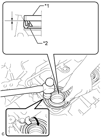
Using SST and a hammer, tap in a new oil seal until its surface is flush with the timing chain cover edge.
Apply MP grease to the lip of the oil seal.
| 16. INSTALL TIMING CHAIN COVER SUB-ASSEMBLY |
Remove any old packing (FIPG) material and be careful not to drop any oil on the contact surfaces of the timing chain cover, cylinder head and cylinder block.
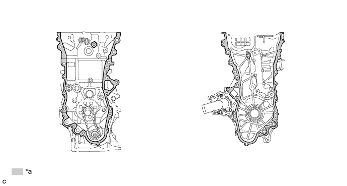
| *a | Clean and degrease | - | - |
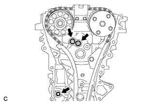 |
Install 3 new O-rings.
Apply seal packing as shown in the illustration.
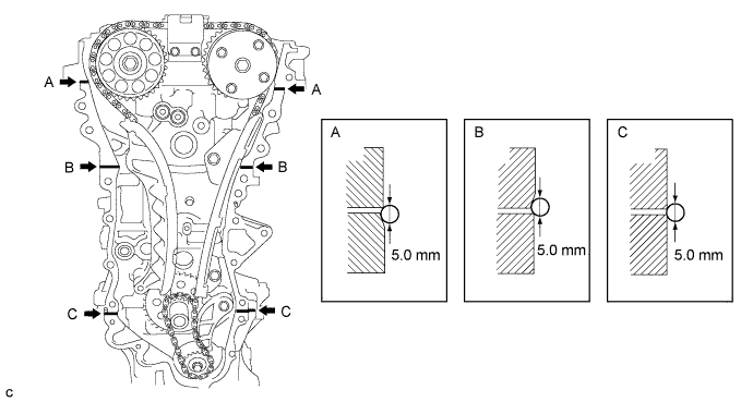
Apply seal packing to the timing chain cover in a line as shown in the following illustration.
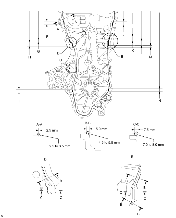
| Item | Seal Packing |
| Dashed line | Toyota Genuine Seal Packing Black, Three Bond 1207B or equivalent |
| Continuous line | |
| Alternate long and short dashed line | Toyota Genuine Seal Packing 1282B, Three Bond 1282B or equivalent |
| Area | Seal Packing Diameter | Distance from Edge of Cover to: | Seal Packing Application Length | Distance from Top of Cover to Top of Seal Packing |
| Dashed line | 2.5 to 3.0 mm (0.0984 to 0.118 in.) | Center of seal packing 2.5 mm (0.0984 in.) | - | - |
| Continuous line | 4.5 to 5.5 mm (0.177 to 0.217 in.) or 7.0 to 8.0 mm (0.276 to 0.315 in.) | - | - | - |
| Alternate long and short dashed line | 4.0 mm (0.157 in.) | Center of seal packing 3.0 mm (0.118 in.) | - | - |
| A - A | 2.5 to 3.5 mm (0.0984 to 0.138 in.) | Center of seal packing 2.5 mm (0.0984 in.) | - | - |
| B - B | 4.5 to 5.5 mm (0.177 to 0.217 in.) | Opposite edge of seal packing 5.0 mm (0.197 in.) | - | - |
| C - C | 7.0 to 8.0 mm (0.276 to 0.315 in.) | Opposite edge of seal packing 7.5 mm (0.295 in.) | - | - |
| F | 4.5 to 5.5 mm (0.177 to 0.217 in.) | - | 15.5 mm (0.610 in.) | 50.4 mm (1.98 in.) |
| G | 4.5 to 5.5 mm (0.177 to 0.217 in.) | - | 10.3 mm (0.406 in.) | 143.1 mm (5.63 in.) |
| H | 7.0 to 8.0 mm (0.276 to 0.315 in.) | - | 19.5 mm (0.768 in.) | 153.4 mm (6.04 in.) |
| I | 4.5 to 5.5 mm (0.177 to 0.217 in.) | - | 16.0 mm (0.630 in.) | 385.8 mm (1.27 ft.) |
| J | 4.5 to 5.5 mm (0.177 to 0.217 in.) | - | 18.6 mm (0.732 in.) | 51.4 mm (2.02 in.) |
| K | 4.5 to 5.5 mm (0.177 to 0.217 in.) | - | 25.3 mm (0.996 in.) | 121.9 mm (4.80 in.) |
| L | 7.0 to 8.0 mm (0.276 to 0.315 in.) | - | 25.8 mm (1.02 in.) | 147.2 mm (5.80 in.) |
| M | 4.5 to 5.5 mm (0.177 to 0.217 in.) | - | 5.1 mm (0.201 in.) | 173.0 mm (6.81 in.) |
| N | 4.5 to 5.5 mm (0.177 to 0.217 in.) | - | 14.6 mm (0.575 in.) | 385.8 mm (1.27 ft.) |
| O | 4.0 mm (0.157 in.) | Center of seal packing 3.0 mm (0.118 in.) | - | - |
Clean the bolt and fitting hole.
Install the timing chain cover.
Temporarily tighten the engine mounting bracket RH with the 3 bolts.
| Item | Length |
| Bolt | 80 mm (3.15 in.) |
Install 2 new O-rings.
Temporarily tighten the oil filter bracket with the 4 bolts.
| Item | Length |
| Bolt | 35 mm (1.38 in.) |
Install the timing chain cover with the 25 bolts and seal washer as shown in the illustration.
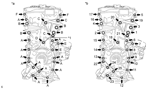
| *1 | Seal Washer | - | - |
| *a | Torque | *b | Bolt Torque Order |
| Item | Length |
| Bolt A, F | 35 mm (1.38 in.) |
| Bolt B | 55 mm (2.16 in.) |
| Bolt C | 80 mm (3.15 in.) |
| Bolt D | 40 mm (1.57 in.) |
| Bolt E | 55 mm (2.16 in.) |
| 17. INSTALL CRANKSHAFT PULLEY |
Align the pulley set key with the key groove of the pulley.
Install the crankshaft pulley to the crankshaft.
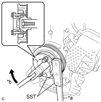 |
Using SST, hold the pulley in place and tighten the bolt.
| *a | Hold |
| *b | Turn |
| 18. INSTALL NO. 1 CHAIN TENSIONER ASSEMBLY |
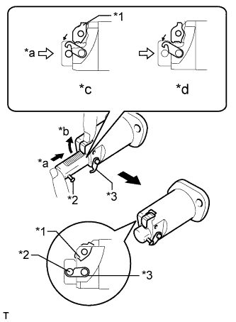 |
Release the cam, and then fully push in the plunger and engage the hook to the pin so that the plunger is in the position shown in the illustration.
| *1 | Cam |
| *2 | Pin |
| *3 | Hook |
| *a | Push |
| *b | Raise |
| *c | CORRECT |
| *d | INCORRECT |
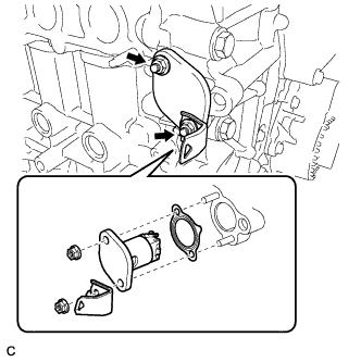 |
Install a new gasket, the bracket and chain tensioner with the 2 nuts.
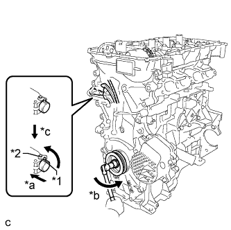 |
Rotate the crankshaft counterclockwise slightly and check that the hook is released.
| *1 | Pin |
| *2 | Hook |
| *a | Push |
| *b | Turn |
| *c | Disconnect |
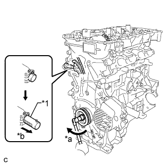 |
Turn the crankshaft clockwise and check that the plunger is extended.
| *1 | Plunger |
| *a | Turn |
| *b | Plunger Extended |
| 19. INSTALL SPARK PLUG TUBE GASKET |
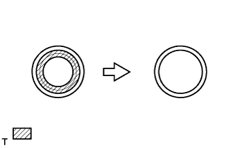 |
Using a cutter knife, cut off the seal part of the removed gasket.
 | Part to Cut Off |
 |
Using a hammer and the plug tube gasket which has had the sealing part cut off, uniformly tap in a new plug tube gasket all the way.
| *1 | Plug Tube Gasket without Sealing Part |
| *2 | New Plug Tube Gasket |
Return the claws of the ventilation baffle plate to their original positions.
| 20. INSTALL CYLINDER HEAD COVER GASKET |
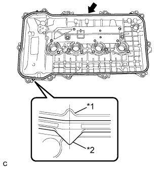 |
Install a new cylinder head cover gasket to the cylinder head cover.
| *1 | Cylinder Head Cover |
| *2 | Cylinder Head Cover Gasket |
| 21. INSTALL CYLINDER HEAD COVER SUB-ASSEMBLY |
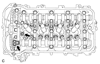 |
Install 2 new gaskets to the camshaft bearing cap.
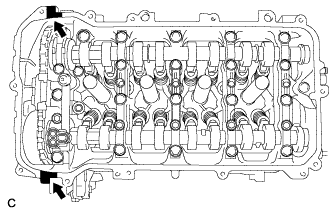 |
Apply seal packing as shown in the illustration.
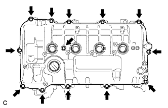 |
Install the cylinder head cover with a new seal washer and the 13 bolts.
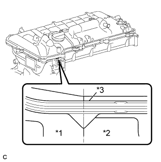 |
| *1 | Timing Chain Cover |
| *2 | Camshaft Housing |
| *3 | Cylinder Head Cover Gasket |
| 22. INSTALL IGNITION COIL ASSEMBLY |
Install the 4 ignition coils with the 4 bolts.
Connect the 4 ignition coil connectors.
| 23. INSTALL FUEL INJECTOR ASSEMBLY |
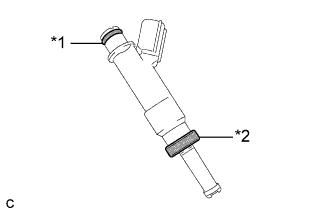 |
Install a new insulator and O-ring to each fuel injector assembly.
| *1 | O-ring |
| *2 | Insulator |
Apply a light coat of gasoline or spindle oil to the contact surfaces of the new O-ring on each fuel injector assembly.
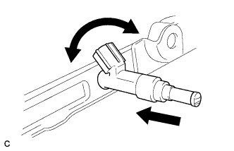 |
While turning the fuel injector assembly left and right, install it onto the fuel delivery pipe sub-assembly.
| 24. INSTALL NO. 1 DELIVERY PIPE SPACER |
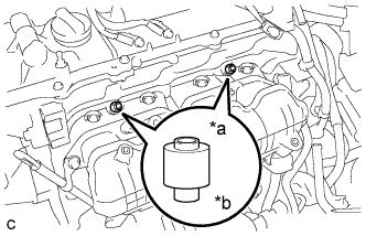 |
Install the 2 No. 1 delivery pipe spacers onto the cylinder head.
| *a | Delivery Pipe Side |
| *b | Cylinder Head Side |
| 25. INSTALL FUEL DELIVERY PIPE SUB-ASSEMBLY |
Install the fuel delivery pipe sub-assembly with the 4 fuel injector assemblies and install the 2 bolts.
Install the bolt to secure the fuel delivery pipe sub-assembly.
| 26. INSTALL FUEL VAPOR FEED PIPE |
Install the fuel vapor feed pipe with the bolt.
| 27. INSTALL INTAKE MANIFOLD |
Install a new No. 1 intake manifold to head gasket to the intake manifold.
Install the intake manifold with the 2 bolts and 2 nuts.
Connect the fuel vapor feed hose and ventilation hose.
Install a new O-ring to the engine oil level dipstick guide sub-assembly.
Apply a light coat of engine oil to the O-ring.
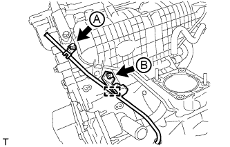 |
Install the engine oil level dipstick guide sub-assembly with the 2 bolts and connect the wire harness clamp.
Install the engine oil level dipstick.
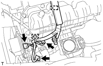 |
Connect the 2 wire harness clamps and 3 connectors.
| 28. INSTALL EGR WITH COOLER PIPE SUB-ASSEMBLY |
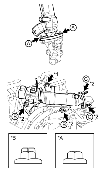 |
Temporarily install a new gasket and the EGR cooler sub-assembly with the 2 nuts (A).
| *A | Nut (C), Type A |
| *B | Nut (C), Type B |
| *1 | Bolt |
| *2 | Stud Bolt and Nut |
Install 2 new gaskets and set the EGR valve with cooler assembly in place.
Using an E8 "TORX" socket wrench, install the 4 stud bolts.
Temporarily install the 4 nuts (B and C) and bolt.
Tighten the 2 nuts (A).
Tighten the 2 nuts (B) and bolt.
Tighten the 2 nuts (C).
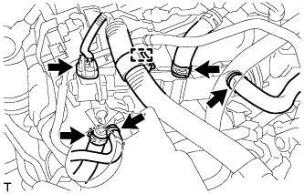 |
Connect the connector, wire harness clamp and 4 water hoses.
| 29. INSTALL EGR VALVE ASSEMBLY |
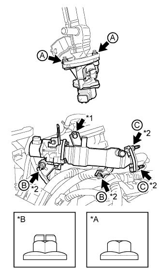 |
Temporarily install a new gasket and the EGR valve assembly with the 2 nuts (A).
| *A | Nut (C), Type A |
| *B | Nut (C), Type B |
| *1 | Bolt |
| *2 | Stud Bolt and Nut |
Install 2 new gaskets and set the EGR valve with cooler assembly in place.
Using an E8 "TORX" socket wrench, install the 4 stud bolts.
Temporarily install the 4 nuts (B and C) and bolt.
Tighten the 2 nuts (A).
Tighten the 2 nuts (B) and bolt.
Tighten the 2 nuts (C).
|
Connect the connector, wire harness clamp and 4 water hoses.
| 30. INSTALL EGR PIPE ASSEMBLY |
Install 2 new gaskets and EGR pipe assembly with the 4 bolts.
Install the wire harness support with the bolt.
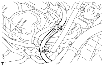 |
Connect the 2 wire harness clamps.
| 31. INSTALL ENGINE OIL LEVEL DIPSTICK GUIDE |
Apply a light coat of engine oil to a new O-ring.
Install the O-ring to the engine oil level dipstick guide.
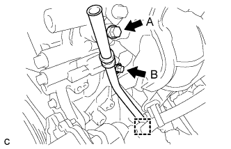 |
Install the engine oil level dipstick guide with the 2 bolts.
Connect the clamp to the engine oil level dipstick guide.
Install the oil dipstick.
| 32. INSTALL THROTTLE BODY ASSEMBLY |
Install a new gasket onto the intake manifold.
Install the throttle body assembly with the 2 bolts and 2 nuts.
Connect the 2 water by-pass hoses and throttle body connector.
| 33. INSTALL ENGINE HANGERS |
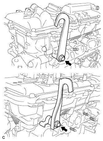 |
Install the 2 engine hangers with the 2 bolts.
| Part Name | Part No. |
| No. 1 engine hanger | 12281-37021 |
| No. 2 engine hanger | 12282-37011 |
| Bolt | 91552-81050 |
| 34. REMOVE ENGINE STAND |
Remove the engine from the engine stand.
| 35. INSTALL ENGINE ASSEMBLY WITH TRANSAXLE |
