CYLINDER HEAD GASKET > INSTALLATION |
| 1. INSPECT NO. 1 VALVE ROCKER ARM SUB-ASSEMBLY |
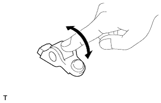 |
Turn the roller by hand to check that it turns smoothly.
If the roller does not turn smoothly, replace the No. 1 valve rocker arm sub-assembly.
| 2. INSPECT VALVE LASH ADJUSTER ASSEMBLY |
Place the lash adjuster into a container filled with new engine oil.
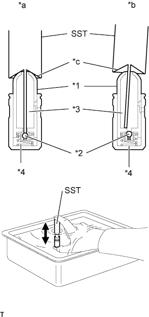 |
Insert the tip of SST into the lash adjuster plunger and use the tip to press down on the check ball inside the plunger.
| *1 | Plunger |
| *2 | Check Ball |
| *3 | Low Pressure Chamber |
| *4 | High Pressure Chamber |
| *a | CORRECT |
| *b | INCORRECT |
| *c | Taper Part |
Squeeze SST and the valve lash adjuster together to move the plunger up and down 5 to 6 times.
Check the movement of the plunger and bleed the air.
After bleeding the air, remove SST. Then try to quickly and firmly press the plunger with your fingers.
| 3. INSPECT CYLINDER HEAD SET BOLT |
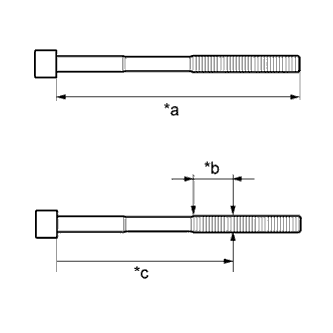 |
Using a vernier caliper, measure the length of the cylinder head set bolt from the seat to the end.
| *a | Measurement Length |
| *b | Measurement Area |
| *c | Distance |
Using a vernier caliper, measure the diameter of the threaded portion of the bolt at its thinnest point.
| 4. INSPECT CYLINDER HEAD |
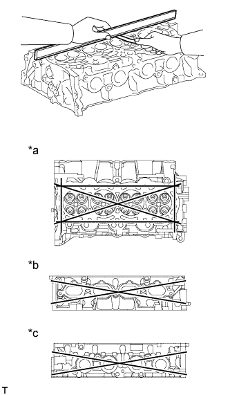 |
Using a precision straightedge and feeler gauge, measure the warpage of the contact surfaces where the cylinder head contacts the cylinder block and manifold.
| *a | Cylinder Head Lower Side: |
| *b | Intake Manifold Side: |
| *c | Exhaust Manifold Side: |
| Item | Specified Condition |
| Cylinder block side | 0.05 mm (0.00197 in.) |
| Intake manifold side | 0.10 mm (0.00394 in.) |
| Exhaust manifold side | 0.10 mm (0.00394 in.) |
| 5. INSTALL CYLINDER HEAD GASKET |
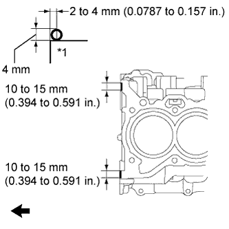 |
Apply seal packing (diameter 4.0 mm (0.157 in.)) to the cylinder block as shown in the illustration.
| *1 | Cylinder Block |
 | Engine Front |
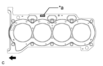 |
Place a new cylinder head gasket on the cylinder block with the Lot No. stamp facing upward.
| *a | Lot No. |
| Engine Front |
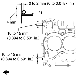 |
Apply seal packing (diameter 4.0 mm (0.157 in.)) to the new cylinder head gasket as shown in the illustration.
| *1 | Cylinder Head Gasket |
| Engine Front |
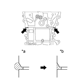 |
After tightening the cylinder head bolts, wipe off any seal packing material that seeped out from the contact surfaces between the cylinder head and cylinder block.
| *a | Before wiping off |
| *b | After wiping off |
| 6. INSTALL CYLINDER HEAD SUB-ASSEMBLY |
Place the cylinder head on the cylinder block.
Install the plate washers to the cylinder head bolts.
Apply a light coat of engine oil to the threads and under the heads of the cylinder head bolts.
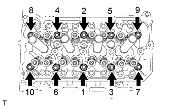 |
Step 1:
Using a 10 mm bi-hexagon wrench, install and uniformly tighten the 10 cylinder head bolts in several steps, in the sequence shown in the illustration.
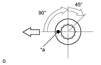 |
Step 2:
| *a | Paint Mark |
 | Engine Front |
Mark each cylinder head bolt head with paint as shown in the illustration.
Tighten the cylinder head bolts 90° in the sequence shown in step 1.
Step 3:
Tighten the cylinder head bolts another 45° in the sequence shown in step 1.
Check that the paint mark is now at a 135° angle to the front.
| 7. INSTALL VALVE STEM CAP |
Apply a light coat of engine oil to the valve stem ends.
Install the 16 valve stem caps to the cylinder head.
| 8. INSTALL VALVE LASH ADJUSTER ASSEMBLY |
Inspect each valve lash adjuster before installing it (Click here).
Install the 16 valve lash adjusters to the cylinder head.
| 9. INSTALL NO. 1 VALVE ROCKER ARM SUB-ASSEMBLY |
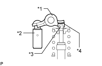 |
Apply engine oil to the valve lash adjuster tips and valve stem cap ends.
| *1 | Valve Rocker Arm |
| *2 | Valve Lash Adjuster |
| *3 | Valve Stem |
| *4 | Valve Stem Cap |
Make sure that the No. 1 valve rocker arms are installed as shown in the illustration.
| 10. INSTALL EXHAUST MANIFOLD |
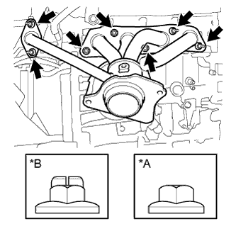 |
Install 2 new gaskets and the exhaust manifold with the 7 nuts.
| *A | Nut Type A |
| *B | Nut Type B |
| 11. INSTALL MANIFOLD STAY |
Install the manifold stay with the 3 bolts.
| 12. INSTALL NO. 1 EXHAUST MANIFOLD HEAT INSULATOR |
Install the No. 1 exhaust manifold heat insulator with the 3 bolts.
| 13. INSTALL CAMSHAFT HOUSING SUB-ASSEMBLY |
