DTC P0A9D-123 Hybrid Battery Temperature Sensor "A" Circuit Low |
DTC P0A9E-123 Hybrid Battery Temperature Sensor "A" Circuit High |
DTC P0AC7-123 Hybrid Battery Temperature Sensor "B" Circuit Low |
DTC P0AC8-123 Hybrid Battery Temperature Sensor "B" Circuit High |
DTC P0ACC-123 Hybrid Battery Temperature Sensor "C" Circuit Low |
DTC P0ACD-123 Hybrid Battery Temperature Sensor "C" Circuit High |
| DTC No. | DTC Detection Condition | Trouble Area |
| P0A9D-123 P0A9E-123 P0AC7-123 P0AC8-123 P0ACC-123 P0ACD-123 | When the temperature of the battery temperature sensor is less than the standard value (open) or higher than the standard value (shorted) (1 trip detection). |
|
| Temperature Displayed | Malfunction |
| -45°C (-49°F) or less | Open or +B short circuit |
| 95°C (203°F) or more | GND short circuit |
| 1.CHECK DTC OUTPUT (HV) |
Connect the intelligent tester to the DLC3.
Turn the power switch on (IG).
Enter the following menus: Powertrain / Hybrid Control / DTC.
Check if DTCs are output.
| Result | Proceed to |
| P0AFC-123 is not output. | A |
| P0AFC-123 is also output. | B |
Turn the power switch off.
|
| ||||
| A | |
 |
| 2.READ VALUE USING INTELLIGENT TESTER |
Connect the intelligent tester to the DLC3.
Turn the power switch on (IG).
Enter the following menus: Powertrain / Hybrid Control / Data List / Temp of Batt TB 1 to 3.
| NEXT | |
|
| 3.CHECK CONNECTOR CONNECTION CONDITION |
Check that the service plug grip is not installed.
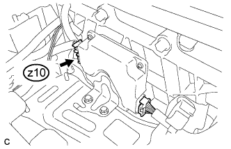 |
Check the connections of connector z10 of the battery smart unit.
|
| ||||
| OK | |
|
| 4.CHECK HV BATTERY (BATTERY TEMPERATURE SENSOR) |
Check that the service plug grip is not installed.
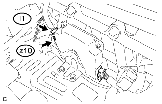 |
Disconnect connectors z10 and i1 from the battery smart unit.
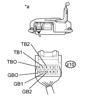 |
Measure the resistance of the circuit for the malfunctioning sensor (battery temperature sensor 0 to 2).
| Tester Connection | Battery Temperature Sensor No. |
| z10-6 (TBO) - z10-12 (GBO) | 0 |
| z10-5 (TB1) - z10-11 (GB1) | 1 |
| z10-4 (TB2) - z10-10 (GB2) | 2 |
| Thermistor Temperature | Switch Condition | Specified Condition |
| 0°C (32°F) | Power switch off | 26.7 to 27.8 kΩ |
| 25°C (77°F) | Power switch off | 9.9 to 10.1 kΩ |
| 40°C (104°F) | Power switch off | 5.73 to 5.92 kΩ |
| *a | Rear view of wire harness connector (to Battery Smart Unit) |
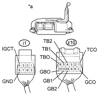 |
Measure the resistance according to the value(s) in the table below.
| Tester Connection | Switch Condition | Standard Resistance |
| z10-6 (TBO) - i1-4 (IGCT) | Power switch off | 10 kΩ or higher |
| z10-6 (TBO) - i1-8 (GND) | Power switch off | 10 kΩ or higher |
| z10-12 (GBO) - i1-4 (IGCT) | Power switch off | 10 kΩ or higher |
| z10-12 (GBO) - i1-8 (GND) | Power switch off | 10 kΩ or higher |
| z10-5 (TB1) - i1-4 (IGCT) | Power switch off | 10 kΩ or higher |
| z10-5 (TB1) - i1-8 (GND) | Power switch off | 10 kΩ or higher |
| z10-11 (GB1) - i1-4 (IGCT) | Power switch off | 10 kΩ or higher |
| z10-11 (GB1) - i1-8 (GND) | Power switch off | 10 kΩ or higher |
| z10-4 (TB2) - i1-4 (IGCT) | Power switch off | 10 kΩ or higher |
| z10-4 (TB2) - i1-8 (GND) | Power switch off | 10 kΩ or higher |
| z10-10 (GB2) - i1-4 (IGCT) | Power switch off | 10 kΩ or higher |
| z10-10 (GB2) - i1-8 (GND) | Power switch off | 10 kΩ or higher |
| z10-1 (TCO) - i1-4 (IGCT) | Power switch off | 10 kΩ or higher |
| z10-1 (TCO) - i1-8 (GND) | Power switch off | 10 kΩ or higher |
| z10-7 (GCO) - i1-4 (IGCT) | Power switch off | 10 kΩ or higher |
| z10-7 (GCO) - i1-8 (GND) | Power switch off | 10 kΩ or higher |
| *a | Rear view of wire harness connector (to Battery Smart Unit) |
Connect the battery smart unit connectors.
|
| ||||
| OK | ||
 | ||
| ||
| 5.CHECK HARNESS AND CONNECTOR (BATTERY TEMPERATURE SENSOR) |
Check that the service plug grip is not installed.
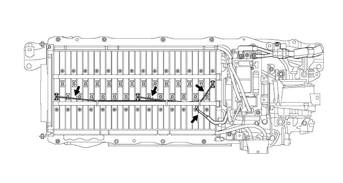
Check the wire harness and connectors of the battery temperature sensor for abnormalities by sight and touch.
|
| ||||
| OK | ||
| ||
| ||


