STEERING GEAR > INSTALLATION |
| 1. INSTALL TIE ROD END SUB-ASSEMBLY LH |
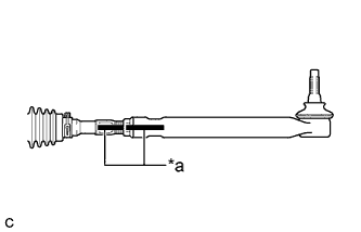 |
Install the lock nut and tie rod end sub-assembly LH to the steering gear assembly until the matchmarks are aligned.
| *a | Matchmark |
| 2. INSTALL TIE ROD END SUB-ASSEMBLY RH |
| 3. INSTALL STEERING LINK ASSEMBLY |
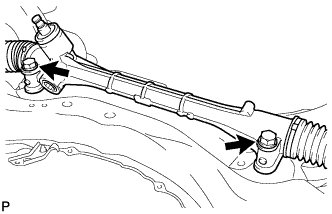 |
Install the steering link assembly to the front suspension crossmember sub-assembly with the 2 bolts and 2 nuts.
| 4. INSTALL STEERING INTERMEDIATE SHAFT |
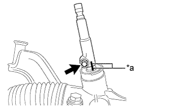 |
Align the matchmarks and install the steering intermediate shaft to the steering link assembly.
| *a | Matchmark |
Install the bolt.
| 5. INSTALL NO. 1 STEERING COLUMN HOLE COVER SUB-ASSEMBLY |
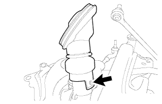 |
Align the round hole in the No. 1 steering column hole cover sub-assembly with the protrusion of the steering link assembly to install the cover.
| 6. INSTALL FRONT SUSPENSION CROSSMEMBER SUB-ASSEMBLY |
Support the front suspension crossmember sub-assembly with an engine lifter using 4 attachments or equivalent tools.
Tighten the bolts on the left and right sides while alternately inserting SST into the left and right side reference holes in the front suspension crossmember sub-assembly.
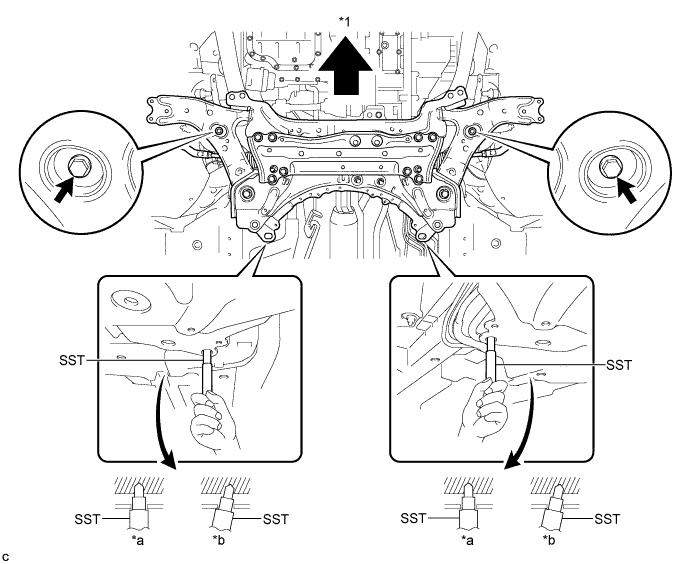
| *1 | Front | - | - |
| *a | OK | *b | NG |
Lower the engine lifter.
Install the rear engine mounting insulator with bolts A and B, and nuts C and D by tightening them in several steps.
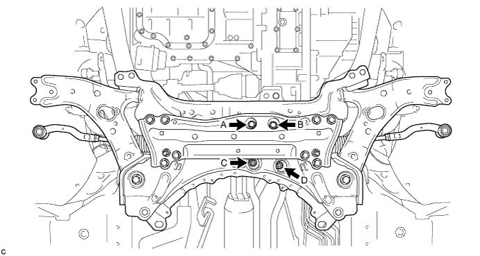
Install the 2 wiring harness clamp brackets with the 2 bolts.
| 7. INSTALL FRONT SUSPENSION MEMBER REAR BRACE LH |
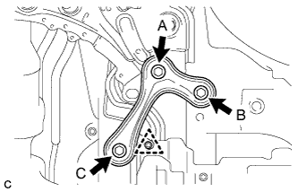 |
Install the front suspension member rear brace LH with the 3 bolts and clip.
| 8. INSTALL FRONT SUSPENSION MEMBER REAR BRACE RH |
| 9. INSTALL REAR SIDE RAIL REINFORCEMENT SUB-ASSEMBLY LH |
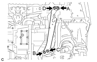 |
Install the rear side rail reinforcement sub-assembly LH with the 4 bolts.
| 10. INSTALL REAR SIDE RAIL REINFORCEMENT SUB-ASSEMBLY RH |
| 11. INSTALL FRONT ENGINE MOUNTING BRACKET LOWER REINFORCEMENT |
Install the front engine mounting bracket lower reinforcement with the 2 bolts.
| 12. CONNECT FRONT LOWER NO. 1 SUSPENSION ARM SUB-ASSEMBLY LH |
Install the front lower No. 1 suspension arm sub-assembly to the front lower ball joint assembly with the bolt and 2 nuts.
| 13. CONNECT FRONT LOWER NO. 1 SUSPENSION ARM SUB-ASSEMBLY RH |
| 14. CONNECT TIE ROD END SUB-ASSEMBLY LH |
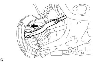 |
Connect the tie rod end sub-assembly LH to the steering knuckle with the nut.
Install a new clip.
| 15. CONNECT TIE ROD END SUB-ASSEMBLY RH |
| 16. INSTALL FRONT STABILIZER LINK ASSEMBLY LH |
Install the front stabilizer link assembly LH to the front stabilizer bar with the nut.
| 17. INSTALL FRONT STABILIZER LINK ASSEMBLY RH |
| 18. CONNECT NO. 1 STEERING COLUMN HOLE COVER SUB-ASSEMBLY |
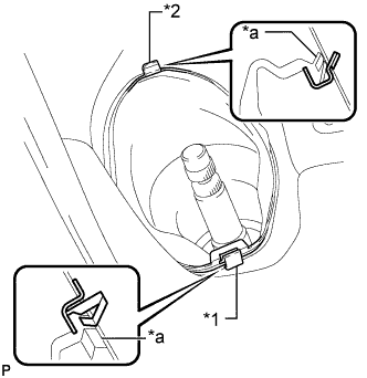 |
Place clip A as shown in the illustration and engage clip B to the body to connect the No. 1 steering column hole cover sub-assembly.
| *1 | Clip A |
| *2 | Clip B |
| *a | Lip |
| 19. CONNECT NO. 2 STEERING INTERMEDIATE SHAFT ASSEMBLY |
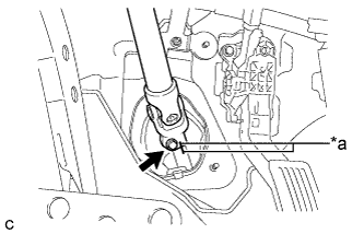 |
Align the matchmarks on the No. 2 steering intermediate shaft assembly and steering intermediate shaft to connect the No. 2 steering intermediate shaft assembly to the steering intermediate shaft.
| *a | Matchmark |
Install the bolt.
| 20. INSTALL COLUMN HOLE COVER SILENCER SHEET |
Install the column hole cover silencer sheet with the 2 clips.
Install the floor carpet.
| 21. INSTALL REAR ENGINE UNDER COVER LH |
| 22. INSTALL REAR ENGINE UNDER COVER RH |
| 23. INSTALL FRONT NO. 3 ENGINE UNDER COVER |
| 24. INSTALL NO. 1 ENGINE UNDER COVER |
| 25. INSTALL FRONT WHEELS |
| 26. STABILIZE SUSPENSION |
Lower the vehicle.
Press down on the vehicle several times to stabilize the suspension.
| 27. INSPECT AND ADJUST FRONT WHEEL ALIGNMENT |
