DTC P3004-132 Power Cable Malfunction |
| DTC No. | INF Code | DTC Detection Condition | Trouble Area |
| P3004 | 132 | The inverter is not precharged. |
|
| 1.CHECK DTC OUTPUT (HYBRID CONTROL) |
Connect the intelligent tester to the DLC3.
Turn the power switch on (IG).
Enter the following menus: Powertrain / Hybrid Control / DTC.
Check if DTCs are output.
| Result | Proceed to |
| P3004-132 only is output. | A |
| DTCs shown in Table 1 are output simultaneously. | B |
| DTCs shown in Table 2 are output simultaneously. | C |
| DTC No. | Relevant Diagnosis |
| P0A1A-151, 155, 156, 658, 659 | Generator Control Module |
| P0A1B-164, 193, 512, 661, 786 | Drive Motor "A" Control Module |
| P0A1D-148 | Hybrid Powertrain Control Module |
| P0A78-266, 267, 586 | Drive Motor "A" Inverter Performance |
| P0A94-442 | DC / DC Converter Performance |
| P0ADB-227 | Hybrid Battery Positive Contactor Control Circuit Low |
| P0ADC-226 | Hybrid Battery Positive Contactor Control Circuit High |
| P0ADF-229 | Hybrid Battery Negative Contactor Control Circuit Low |
| P0AE0-228 | Hybrid Battery Negative Contactor Control Circuit High |
| P0AE6-225 | Hybrid Battery Precharge Contactor Control Circuit Low |
| P0AE7-224 | Hybrid Battery Precharge Contactor Control Circuit High |
| P0C76-523 | Hybrid Battery System Discharge Time Too Long |
| P2511-149 | ECM/PCM Power Relay Sensor Circuit Intermittent |
| P3004-131, 800, 801 | Power Cable Malfunction |
| P324E-788 | MG-ECU Power Relay Intermittent Circuit |
| U0110 (all INF codes)*1 | Lost Communication with Drive Motor Control Module |
| DTC No. | Relevant Diagnosis |
| P0A95-123 | High Voltage Fuse |
| P0ABF-123 | Hybrid Battery Pack Current Sensor Circuit |
| P0AC0-123 | Hybrid Battery Pack Current Sensor Circuit Range / Performance |
| P0AC1-123 | Hybrid Battery Pack Current Sensor "A" Circuit Low |
| P0AC2-123 | Hybrid Battery Pack Current Sensor "A" Circuit High |
| P0AFC-123 | Hybrid Battery Pack Sensor Module |
| P0B3D-123 | Hybrid Battery Voltage Sensor "A" Circuit Low |
| P0B42-123 | Hybrid Battery Voltage Sensor "B" Circuit Low |
| P0B47-123 | Hybrid Battery Voltage Sensor "C" Circuit Low |
| P0B4C-123 | Hybrid Battery Voltage Sensor "D" Circuit Low |
| P0B51-123 | Hybrid Battery Voltage Sensor "E" Circuit Low |
| P0B56-123 | Hybrid Battery Voltage Sensor "F" Circuit Low |
| P0B5B-123 | Hybrid Battery Voltage Sensor "G" Circuit Low |
| P0B60-123 | Hybrid Battery Voltage Sensor "H" Circuit Low |
| P0B65-123 | Hybrid Battery Voltage Sensor "I" Circuit Low |
| P0B6A-123 | Hybrid Battery Voltage Sensor "J" Circuit Low |
| P0B6F-123 | Hybrid Battery Voltage Sensor "K" Circuit Low |
| P0B74-123 | Hybrid Battery Voltage Sensor "L" Circuit Low |
| P0B79-123 | Hybrid Battery Voltage Sensor "M" Circuit Low |
| P0B7E-123 | Hybrid Battery Voltage Sensor "N" Circuit Low |
| P0B83-123 | Hybrid Battery Voltage Sensor "O" Circuit Low |
| P308A-123 | Hybrid Battery Voltage Sensor All Circuits Low |
| U029A-123 | Lost Communication with Hybrid Battery Pack Sensor Module |
Turn the power switch off.
|
| ||||
|
| ||||
| A | |
 |
| 2.CHECK FREEZE FRAME DATA (HYBRID CONTROL) |
Connect the intelligent tester to the DLC3.
Turn the power switch on (IG).
Enter the following menus: Powertrain / Hybrid Control / DTC.
Read the freeze frame data of DTC P3004-132.
| Result | Proceed to |
All of the following conditions are met:
| A |
| In addition to the above conditions, HV battery current (Batt Pack Current Val) is 3 A or more. | B |
| Other than above | C |
Turn the power switch off.
|
| ||||
|
| ||||
| A | ||
 | ||
| ||
| 3.CHECK CONNECTOR CONNECTION CONDITION (POWER MANAGEMENT CONTROL ECU CONNECTOR) |
Check the connections of the power management control ECU connectors.
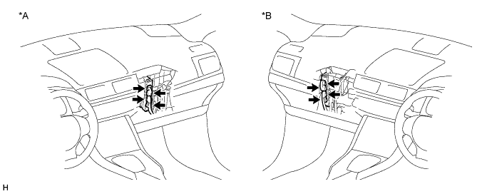
| *A | for LHD | *B | for RHD |
|
| ||||
| OK | |
|
| 4.CHECK FRAME WIRE (INVERTER WITH CONVERTER ASSEMBLY SIDE) |
Check that the service plug grip is not installed.
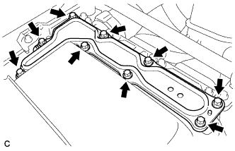 |
Remove the inverter cover from the inverter with converter assembly.
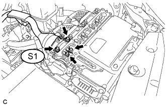 |
Check the connection between the frame wire S1 and the inverter with converter assembly.
Install the inverter cover to the inverter with converter assembly.
|
| ||||
| OK | |
|
| 5.CHECK FRAME WIRE (HYBRID BATTERY JUNCTION BLOCK ASSEMBLY SIDE) |
Check that the service plug grip is not installed.
Remove the upper hybrid battery cover sub-assembly (Click here).
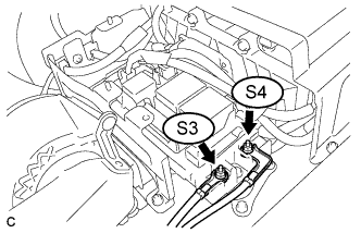 |
Check the connection between the frame wire S4, S3 and the hybrid battery junction block assembly.
Check for arc marks on the terminals of the frame wire.
| Result | Proceed to | |
| The terminals are connected securely and there are no contact problems. | There are no arc marks. | A |
| The terminals are not connected securely and there is a contact problem. | There are arc marks. | B |
| The terminals are not connected securely and there is a contact problem. | There are no arc marks. | C |
| The terminals are connected securely and there are no contact problems. | There are arc marks. | B |
Install the upper hybrid battery cover sub-assembly (Click here).
|
| ||||
|
| ||||
| A | |
|
| 6.CHECK FRAME WIRE (INVERTER WITH CONVERTER - HYBRID BATTERY JUNCTION BLOCK) |
Check that the service plug grip is not installed.
|
Remove the inverter cover from the inverter with converter assembly.
Remove the upper hybrid battery cover sub-assembly (Click here).
|
Disconnect the frame wire S1 from the inverter with converter assembly.
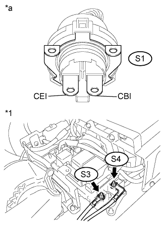 |
Measure the resistance according to the value(s) in the table below.
| Tester Connection | Switch Condition | Specified Condition |
| S4-1 (CBI) - S1-2 (CBI) | Power switch off | Below 1 Ω |
| S3-1 (CEI) - S1-1 (CEI) | Power switch off | Below 1 Ω |
| *1 | Frame Wire (Hybrid Battery Junction Block Assembly Side) |
| *a | Front view of Frame Wire connector (to Inverter with Converter Assembly) |
Connect the frame wire from the inverter with converter assembly.
Install the upper hybrid battery cover sub-assembly (Click here).
Install the inverter cover to the inverter with converter assembly.
|
| ||||
| OK | |
|
| 7.CHECK CONDITION OF MAIN BATTERY CABLE CONNECTION(S) |
Check that the service plug grip is not installed.
Remove the upper hybrid battery cover sub-assembly (Click here).
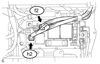 |
Check the connections between the main battery cables f2, h2 and the hybrid battery junction block assembly.
Check for arc marks on the terminals of the main battery cable connectors.
| Result | Proceed to | |
| The terminals are connected securely and there are no contact problems. | There are no arc marks. | A |
| The terminals are not connected securely and there is a contact problem. | There are arc marks. | B |
| The terminals are not connected securely and there is a contact problem. | There are no arc marks. | C |
| The terminals are connected securely and there are no contact problems. | There are arc marks. | B |
Install the upper hybrid battery cover sub-assembly (Click here).
|
| ||||
|
| ||||
| A | |
|
| 8.CHECK HV BATTERY |
Check that the service plug grip is not installed.
Remove the upper hybrid battery cover sub-assembly (Click here).
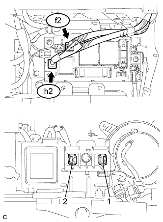 |
Measure the voltage according to the value(s) in the table below.
| Tester Connection | Switch Condition | Specified Condition |
| f2-1 (+) - 2 | Power switch off | 114 to 190 V |
| h2-1 (-) - 1 | Power switch off | 54 to 90 V |
Install the upper hybrid battery cover sub-assembly (Click here).
|
| ||||
| OK | |
|
| 9.CHECK HARNESS AND CONNECTOR (POWER MANAGEMENT CONTROL ECU - HYBRID BATTERY JUNCTION BLOCK) |
Check that the service plug grip is not installed.
Disconnect connector H3 from the power management control ECU.
Remove the upper hybrid battery cover sub-assembly (Click here).
Disconnect the connector i3 that drives the relay of the hybrid battery junction block assembly.
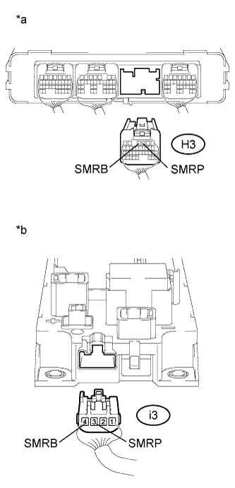 |
Measure the resistance according to the value(s) in the table below.
| Tester Connection | Switch Condition | Specified Condition |
| H3-4 (SMRB) - i3-4 (SMRB) | Power switch off | Below 1 Ω |
| H3-3 (SMRP) - i3-3 (SMRP) | Power switch off | Below 1 Ω |
| *a | Rear view of wire harness connector (to Power Management Control ECU) |
| *b | Rear view of wire harness connector (to Hybrid Battery Junction Block Assembly) |
Connect the hybrid battery junction block assembly connector.
Install the upper hybrid battery cover sub-assembly (Click here).
Connect the power management control ECU connector.
|
| ||||
| OK | |
|
| 10.INSPECT HYBRID BATTERY JUNCTION BLOCK ASSEMBLY (SMRB) |
Check that the service plug grip is not installed.
Remove the hybrid battery junction block assembly (Click here).
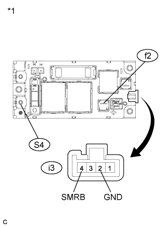 |
Measure the resistance according to the value(s) in the table below.
| Tester Connection | Switch Condition | Specified Condition |
| f2-1 (+) - S4-1 (CBI) | Auxiliary battery voltage is applied between terminals i3-4 (SMRB) and i3-2 (GND). | Below 1 Ω |
| *1 | Hybrid Battery Junction Block Assembly |
Measure the resistance according to the value(s) in the table below.
| Tester Connection | Condition | Specified Condition |
| i3-4 (SMRB) - i3-2 (GND) | -40 to 80°C (-40 to 176°F) | 19.0 to 35.5 Ω |
Install the hybrid battery junction block assembly (Click here).
|
| ||||
| OK | |
|
| 11.INSPECT HYBRID BATTERY JUNCTION BLOCK ASSEMBLY (SMRP) |
Check that the service plug grip is not installed.
Remove the hybrid battery junction block assembly (Click here).
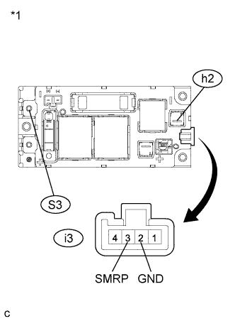 |
Measure the resistance according to the value(s) in the table below.
| Tester Connection | Switch Condition | Specified Condition |
| h2-1 (-) - S3-1 (CEI) | Auxiliary battery voltage is applied between terminals i3-3 (SMRP) and i3-2 (GND). | 28.5 to 31.5 Ω |
| *1 | Hybrid Battery Junction Block Assembly |
Measure the resistance according to the value(s) in the table below.
| Tester Connection | Condition | Specified Condition |
| i3-3 (SMRP) - i3-2 (GND) | -40 to 80°C (-40 to 176°F) | 112 to 274 Ω |
Install the hybrid battery junction block assembly (Click here).
|
| ||||
| OK | |
|
| 12.CHECK FOR INTERMITTENT PROBLEMS |
Check for intermittent problems (Click here).
| NEXT | |
|
| 13.CLEAR DTC |
Connect the intelligent tester to the DLC3.
Turn the power switch on (IG).
Enter the following menus: Powertrain / Hybrid Control / DTC.
Read and record the DTCs and freeze frame data.
Clear DTCs and freeze frame data.
Turn the power switch off.
| NEXT | |
|
| 14.CHECK DTC OUTPUT (HYBRID CONTROL) |
Connect the intelligent tester to the DLC3.
Turn the power switch on (READY).
Enter the following menus: Powertrain / Hybrid Control / DTC.
Check if DTCs are output.
| Result | Proceed to |
| No DTCs are output. | A |
| DTC P3004-131 is output. | B |
| DTC P3004-132 is output. | C |
Turn the power switch off.
|
| ||||
|
| ||||
| A | ||
| ||
| ||


