DTC B2312 Power Window Switch Malfunction |
| DTC No. | DTC Detection Condition | Trouble Area |
| B2312 |
| Multiplex network master switch assembly |
| DTC No. | DTC Detection Condition | Trouble Area |
| B2312 |
|
|
| DTC No. | DTC Detection Condition | Trouble Area |
| B2312 |
|
|
| DTC No. | DTC Detection Condition | Trouble Area |
| B2312 |
|
|
| DTC No. | DTC Detection Condition | Trouble Area |
| B2312 |
|
|
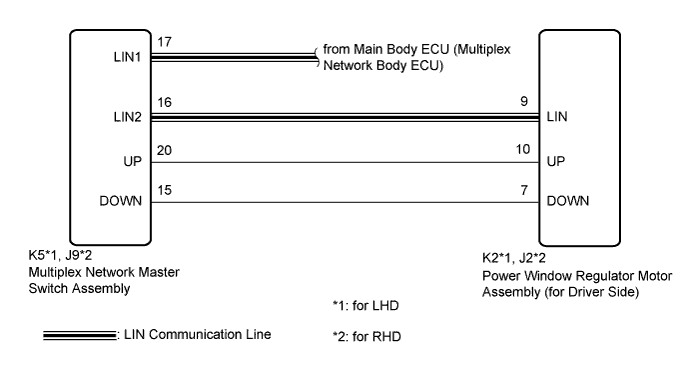
| for Driver Side |
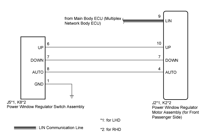
| for Front Passenger Side |
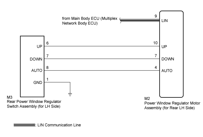
| for Rear LH Side |
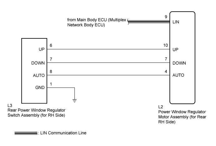
| for Rear RH Side |
| 1.CHECK FOR DTC |
Clear the DTCs (Click here).
Check for DTCs (Click here).
|
| ||||
| OK | ||
 | ||
| ||
| 2.CHECK DTC OUTPUT |
Check the parts which the DTCs have been output from.
| Result | Proceed to |
| DTC output from multiplex network master switch assembly | A |
| DTC output from power window regulator motor assembly (for driver side) | B |
| DTC output from power window regulator motor assembly (for front passenger side) | C |
| DTC output from power window regulator motor assembly (for rear LH side) | D |
| DTC output from power window regulator motor assembly (for rear RH side) | E |
|
| ||||
|
| ||||
|
| ||||
|
| ||||
| A | ||
| ||
| ||
| 3.READ VALUE USING INTELLIGENT TESTER (D-Door Motor) |
Connect the intelligent tester to the DLC3.
Turn the power switch on (IG).
Turn the intelligent tester on.
Enter the following menus: Body / D-Door Motor / Data List.
Read the Data List according to the display on the intelligent tester.
| Tester Display | Measurement Item/Range | Normal Condition | Diagnostic Note |
| D Door P/W Up SW | Driver door power window manual up switch signal / ON or OFF | ON: Driver door power window manual up switch operated OFF: Driver door power window manual up switch not operated | - |
| D Door P/W Down SW | Driver door power window manual down switch signal / ON or OFF | ON: Driver door power window manual down switch operated OFF: Driver door power window manual down switch not operated | - |
|
| ||||
| OK | ||
| ||
| ||
| 4.CHECK HARNESS AND CONNECTOR (MASTER SWITCH - DRIVER SIDE MOTOR) |
Disconnect the multiplex network master switch assembly connector.
Disconnect the power window regulator motor assembly (for driver side) connector.
Measure the resistance according to the value(s) in the table below.
| Tester Connection | Condition | Specified Condition |
| K5-20 (UP) - Body ground | Always | 10 kΩ or higher |
| K5-15 (DOWN) - Body ground | Always | 10 kΩ or higher |
| K2-10 (UP) - Body ground | Always | 10 kΩ or higher |
| K2-7 (DOWN) - Body ground | Always | 10 kΩ or higher |
| Tester Connection | Condition | Specified Condition |
| J9-20 (UP) - Body ground | Always | 10 kΩ or higher |
| J9-15 (DOWN) - Body ground | Always | 10 kΩ or higher |
| J2-10 (UP) - Body ground | Always | 10 kΩ or higher |
| J2-7 (DOWN) - Body ground | Always | 10 kΩ or higher |
|
| ||||
| OK | |
 |
| 5.REPLACE MULTIPLEX NETWORK MASTER SWITCH ASSEMBLY |
Replace the multiplex network master switch assembly (Click here).
| NEXT | |
|
| 6.CHECK FOR DTC |
Clear the DTCs (Click here).
Check for DTCs (Click here).
|
| ||||
| OK | ||
| ||
| ||
| 7.READ VALUE USING INTELLIGENT TESTER (P-Door Motor) |
Connect the intelligent tester to the DLC3.
Turn the power switch on (IG).
Turn the intelligent tester on.
Enter the following menus: Body / P-Door Motor / Data List.
Read the Data List according to the display on the intelligent tester.
| Tester Display | Measurement Item/Range | Normal Condition | Diagnostic Note |
| P Door P/W Auto SW | Front passenger side power window auto up and down switch signal / ON or OFF | ON: Front passenger side door power window auto switch operated OFF: Front passenger side door power window auto switch not operated | - |
| P Door P/W Up SW | Front passenger side power window manual up switch signal / ON or OFF | ON: Front passenger side door power window manual up switch operated OFF: Front passenger side door power window manual up switch not operated | - |
| P Door P/W Down SW | Front passenger side power window manual down switch signal / ON or OFF | ON: Front passenger side door power window manual down switch operated OFF: Front passenger side door power window manual down switch not operated | - |
|
| ||||
| OK | ||
| ||
| ||
| 8.INSPECT POWER WINDOW REGULATOR SWITCH ASSEMBLY |
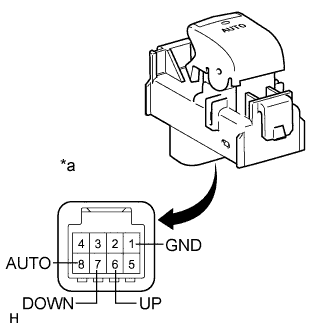 |
Remove the power window regulator switch assembly (Click here).
Measure the resistance according to the value(s) in the table below.
| Tester Connection | Switch Condition | Specified Condition |
| 6 (UP) - 1 (GND) | Auto up or up position | Below 1 Ω |
| 7 (DOWN) - 1 (GND) | Auto down or down position | Below 1 Ω |
| 8 (AUTO) - 1 (GND) | Auto up or auto down position | Below 1 Ω |
| 6 (UP) - 1 (GND) | Free | 10 kΩ or higher |
| 7 (DOWN) - 1 (GND) | Free | 10 kΩ or higher |
| 8 (AUTO) - 1 (GND) | Free | 10 kΩ or higher |
| *a | Component without harness connected (Power Window Regulator Switch Assembly) |
|
| ||||
| OK | |
|
| 9.CHECK HARNESS AND CONNECTOR (FRONT PASSENGER SIDE SWITCH - FRONT PASSENGER SIDE MOTOR) |
Disconnect the power window regulator motor assembly (for front passenger side) connector.
Measure the resistance according to the value(s) in the table below.
| Tester Connection | Condition | Specified Condition |
| J5-6 (UP) - Body ground | Always | 10 kΩ or higher |
| J5-8 (AUTO) - Body ground | Always | 10 kΩ or higher |
| J5-7 (DOWN) - Body ground | Always | 10 kΩ or higher |
| J2-10 (UP) - Body ground | Always | 10 kΩ or higher |
| J2-4 (AUTO) - Body ground | Always | 10 kΩ or higher |
| J2-7 (DOWN) - Body ground | Always | 10 kΩ or higher |
| Tester Connection | Condition | Specified Condition |
| K8-6 (UP) - Body ground | Always | 10 kΩ or higher |
| K8-8 (AUTO) - Body ground | Always | 10 kΩ or higher |
| K8-7 (DOWN) - Body ground | Always | 10 kΩ or higher |
| K2-10 (UP) - Body ground | Always | 10 kΩ or higher |
| K2-4 (AUTO) - Body ground | Always | 10 kΩ or higher |
| K2-7 (DOWN) - Body ground | Always | 10 kΩ or higher |
|
| ||||
| OK | ||
| ||
| ||
| 10.READ VALUE USING INTELLIGENT TESTER (RL-Door Motor) |
Connect the intelligent tester to the DLC3.
Turn the power switch on (IG).
Turn the intelligent tester on.
Enter the following menus: Body / RL-Door Motor / Data List.
Read the Data List according to the display on the intelligent tester.
| Tester Display | Measurement Item/Range | Normal Condition | Diagnostic Note |
| RL Door P/W Auto SW | Rear LH side power window auto up and down switch signal / ON or OFF | ON: Rear LH door power window auto switch operated OFF: Rear LH door power window auto switch not operated | - |
| RL Door P/W Up SW | Rear LH side power window manual up switch signal / ON or OFF | ON: Rear LH door power window manual up switch operated OFF: Rear LH door power window manual up switch not operated | - |
| RL Door P/W Down SW | Rear LH side power window manual down switch signal / ON or OFF | ON: Rear LH door power window manual down switch operated OFF: Rear LH door power window manual down switch not operated | - |
|
| ||||
| OK | ||
| ||
| ||
| 11.INSPECT REAR POWER WINDOW REGULATOR SWITCH ASSEMBLY (for LH Side) |
|
Remove the rear power window regulator switch assembly (for LH side) (Click here).
Measure the resistance according to the value(s) in the table below.
| Tester Connection | Switch Condition | Specified Condition |
| 6 (UP) - 1 (GND) | Auto up or up position | Below 1 Ω |
| 7 (DOWN) - 1 (GND) | Auto down or down position | Below 1 Ω |
| 8 (AUTO) - 1 (GND) | Auto up or auto down position | Below 1 Ω |
| 6 (UP) - 1 (GND) | Free | 10 kΩ or higher |
| 7 (DOWN) - 1 (GND) | Free | 10 kΩ or higher |
| 8 (AUTO) - 1 (GND) | Free | 10 kΩ or higher |
| *a | Component without harness connected (Rear Power Window Regulator Switch Assembly (for LH Side)) |
|
| ||||
| OK | |
|
| 12.CHECK HARNESS AND CONNECTOR (REAR LH SWITCH - REAR LH MOTOR) |
Disconnect the power window regulator motor assembly (for rear LH side) connector.
Measure the resistance according to the value(s) in the table below.
| Tester Connection | Condition | Specified Condition |
| M3-6 (UP) - Body ground | Always | 10 kΩ or higher |
| M3-7 (DOWN) - Body ground | Always | 10 kΩ or higher |
| M3-8 (AUTO) - Body ground | Always | 10 kΩ or higher |
| M2-10 (UP) - Body ground | Always | 10 kΩ or higher |
| M2-7 (DOWN) - Body ground | Always | 10 kΩ or higher |
| M2-4 (AUTO) - Body ground | Always | 10 kΩ or higher |
|
| ||||
| OK | ||
| ||
| ||
| 13.READ VALUE USING INTELLIGENT TESTER (RR-Door Motor) |
Connect the intelligent tester to the DLC3.
Turn the power switch on (IG).
Turn the intelligent tester on.
Enter the following menus: Body / RR-Door Motor / Data List.
Read the Data List according to the display on the intelligent tester.
| Tester Display | Measurement Item/Range | Normal Condition | Diagnostic Note |
| RR Door P/W Auto SW | Rear RH side power window auto up and down switch signal / ON or OFF | ON: Rear RH door power window auto switch operated OFF: Rear RH door power window auto switch not operated | - |
| RR Door P/W Up SW | Rear RH side power window manual up switch signal / ON or OFF | ON: Rear RH door power window manual up switch operated OFF: Rear RH door power window manual up switch not operated | - |
| RR Door P/W Down SW | Rear RH side power window manual down switch signal / ON or OFF | ON: Rear RH door power window manual down switch operated OFF: Rear RH door power window manual down switch not operated | - |
|
| ||||
| OK | ||
| ||
| ||
| 14.INSPECT REAR POWER WINDOW REGULATOR SWITCH ASSEMBLY (for RH Side) |
|
Remove the rear power window regulator switch assembly (for RH side) (Click here).
Measure the resistance according to the value(s) in the table below.
| Tester Connection | Switch Condition | Specified Condition |
| 6 (UP) - 1 (GND) | Auto up or up position | Below 1 Ω |
| 7 (DOWN) - 1 (GND) | Auto down or down position | Below 1 Ω |
| 8 (AUTO) - 1 (GND) | Auto up or auto down position | Below 1 Ω |
| 6 (UP) - 1 (GND) | Free | 10 kΩ or higher |
| 7 (DOWN) - 1 (GND) | Free | 10 kΩ or higher |
| 8 (AUTO) - 1 (GND) | Free | 10 kΩ or higher |
| *a | Component without harness connected (Rear Power Window Regulator Switch Assembly (for RH Side)) |
|
| ||||
| OK | |
|
| 15.CHECK HARNESS AND CONNECTOR (REAR RH SWITCH - REAR RH MOTOR) |
Disconnect the power window regulator motor assembly (for rear RH side) connector.
Measure the resistance according to the value(s) in the table below.
| Tester Connection | Condition | Specified Condition |
| L3-6 (UP) - Body ground | Always | 10 kΩ or higher |
| L3-7 (DOWN) - Body ground | Always | 10 kΩ or higher |
| L3-8 (AUTO) - Body ground | Always | 10 kΩ or higher |
| L2-10 (UP) - Body ground | Always | 10 kΩ or higher |
| L2-7 (DOWN) - Body ground | Always | 10 kΩ or higher |
| L2-4 (AUTO) - Body ground | Always | 10 kΩ or higher |
|
| ||||
| OK | ||
| ||
| ||


