DTC B1242 Wireless Door Lock Tuner Circuit Malfunction |
| DTC No. | DTC Detection Condition | Trouble Area |
| B1242 |
|
|
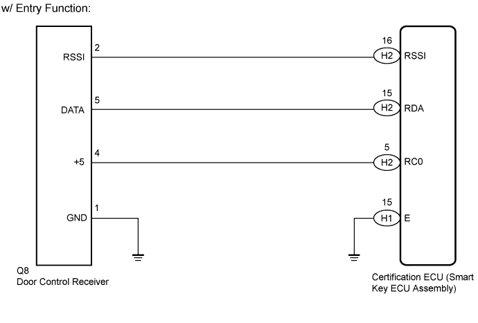
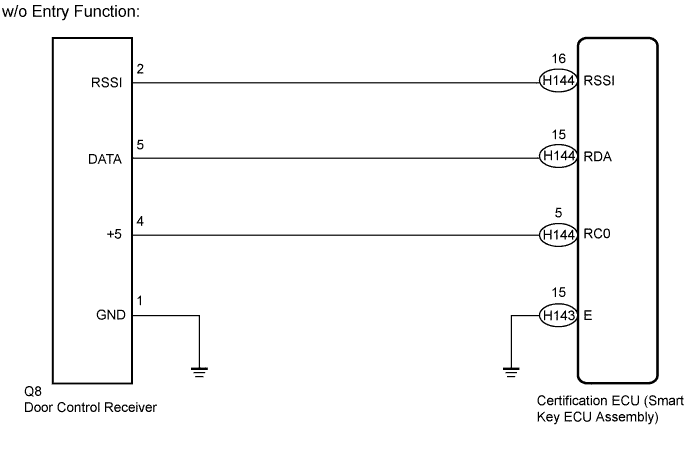
| 1.CHECK HARNESS AND CONNECTOR (DOOR CONTROL RECEIVER - CERTIFICATION ECU AND BODY GROUND) |
Disconnect the H1 and H2 certification ECU (smart key ECU assembly) connectors.*1
Disconnect the H143 and H144 certification ECU (smart key ECU assembly) connectors.*2
Disconnect the Q8 door control receiver connector.
Measure the resistance according to the value(s) in the table below.
| Tester Connection | Condition | Specified Condition |
| H2-16 (RSSI) - Q8-2 (RSSI) | Always | Below 1 Ω |
| H2-15 (RDA) - Q8-5 (DATA) | Always | Below 1 Ω |
| H2-5 (RC0) - Q8-4 (+5) | Always | Below 1 Ω |
| H1-15 (E) - Body ground | Always | Below 1 Ω |
| Q8-1 (GND) - Body ground | Always | Below 1 Ω |
| H2-16 (RSSI) or Q8-2 (RSSI) - Body ground | Always | 10 kΩ or higher |
| H2-15 (RDA) or Q8-5 (DATA) - Body ground | Always | 10 kΩ or higher |
| H2-5 (RC0) or Q8-4 (+5) - Body ground | Always | 10 kΩ or higher |
| Tester Connection | Condition | Specified Condition |
| H144-16 (RSSI) - Q8-2 (RSSI) | Always | Below 1 Ω |
| H144-15 (RDA) - Q8-5 (DATA) | Always | Below 1 Ω |
| H144-5 (RC0) - Q8-4 (+5) | Always | Below 1 Ω |
| H143-15 (E) - Body ground | Always | Below 1 Ω |
| Q8-1 (GND) - Body ground | Always | Below 1 Ω |
| H144-16 (RSSI) or Q8-2 (RSSI) - Body ground | Always | 10 kΩ or higher |
| H144-15 (RDA) or Q8-5 (DATA) - Body ground | Always | 10 kΩ or higher |
| H144-5 (RC0) or Q8-4 (+5) - Body ground | Always | 10 kΩ or higher |
|
| ||||
| OK | |
 |
| 2.CHECK CERTIFICATION ECU (SMART KEY ECU ASSEMBLY) |
Reconnect the H1 and H2 certification ECU (smart key ECU assembly) connectors.*1
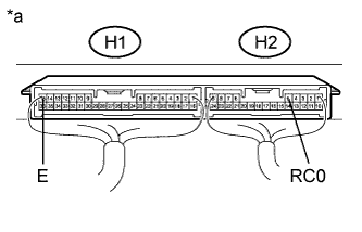 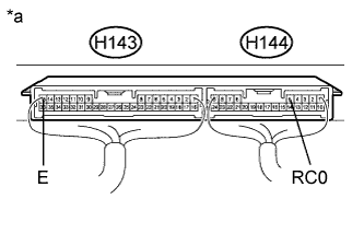 |
Reconnect the H143 and H144 certification ECU (smart key ECU assembly) connectors.*2
*1: w/ Entry Function
*2: w/o Entry Function
Reconnect the Q8 door control receiver connector.
Measure the voltage according to the value(s) in the table below.
| Tester Connection | Condition | Specified Condition |
| H2-5 (RC0) - H1-15 (E) | Power switch off, all doors closed and electrical key transmitter switch pressed | 4.5 to 5.5 V |
| Tester Connection | Condition | Specified Condition |
| H144-5 (RC0) - H143-15 (E) | Power switch off, all doors closed and electrical key transmitter switch pressed | 4.5 to 5.5 V |
| *a | Component with harness connected (Certification ECU (Smart Key ECU Assembly)) |
|
| ||||
| OK | |
|
| 3.REPLACE DOOR CONTROL RECEIVER |
Temporarily replace the door control receiver with a new one (Click here).
| NEXT | |
|
| 4.CHECK FOR DTC |
Clear the DTCs (Click here).
Recheck for DTCs.
|
| ||||
| OK | ||
 | ||
| ||

