ENTRY AND START SYSTEM (for Entry Function) > Back Door Entry Unlock Function does not Operate |
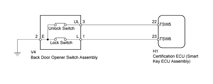
| 1.READ VALUE USING INTELLIGENT TESTER (ENTRY BACK DOOR OPEN FUNCTION) |
Connect the intelligent tester to the DLC3.
Turn the power switch on (IG).
Turn the intelligent tester on.
Enter the following menus: Body / Entry & Start / Data List.
Read the Data List according to the display on the intelligent tester.
| Tester Display | Measurement Item/Range | Normal Condition | Diagnostic Note |
| B-Dr Opening Operation | Back door opening operation / Long, Twice, OFF | Customization status displayed | - |
| Result | Proceed to |
| Customize setting is Long or Twice. | A |
| Customize setting is OFF. | B |
|
| ||||
| A | |
 |
| 2.CHECK POWER DOOR LOCK OPERATION |
When the door control switch on the multiplex network master switch assembly is operated, check that the doors unlock and lock according to the switch operation (Click here).
|
| ||||
| OK | |
|
| 3.PERFORM ACTIVE TEST USING INTELLIGENT TESTER |
Enter the following menus: Body / Main Body / Active Test.
Perform the Active Test according to the display on the intelligent tester.
| Tester Display | Measurement Item/Range | Normal Condition | Diagnostic Note |
| Trunk and Back-Door Open | Operate back door lock motor | ON or OFF | - |
|
| ||||
| OK | |
|
| 4.READ VALUE USING INTELLIGENT TESTER (UNLOCK SWITCH) |
Using the intelligent tester, read the Data List (Click here).
| Tester Display | Measurement Item/Range | Normal Condition | Diagnostic Note |
| Tr/B Door Unlock SW | Back door opener switch (unlock switch) / ON or OFF | ON: Back door opener switch (unlock switch) pushed OFF: Back door opener switch (unlock switch) not pushed |
|
|
| ||||
| OK | ||
 | ||
| ||
| 5.CHECK HARNESS AND CONNECTOR (BACK DOOR OPENER SWITCH ASSEMBLY - CERTIFICATION ECU) |
Disconnect the V4 back door opener switch assembly connector.
Disconnect the H1 certification ECU (smart key ECU assembly) connector.
Measure the resistance according to the value(s) in the table below.
| Tester Connection | Condition | Specified Condition |
| V4-3 (UL) - H1-22 (TSW5) | Always | Below 1 Ω |
| V4-2 (E) - Body ground | Always | Below 1 Ω |
| V4-3 (UL) or H1-22 (TSW5) - Body ground | Always | 10 kΩ or higher |
|
| ||||
| OK | |
|
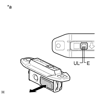
| 6.INSPECT BACK DOOR OPENER SWITCH ASSEMBLY (UNLOCK SWITCH) |
 |
Remove the back door opener switch assembly (Click here).
Measure the resistance according to the value(s) in the table below.
| Tester Connection | Switch Condition | Specified Condition |
| 3 (UL) - 2 (E) | No switch pushed | 10 kΩ or higher |
| 3 (UL) - 2 (E) | Unlock switch pushed | Below 1 Ω |
| *a | Component without harness connected (Back Door Opener Switch Assembly) |
|
| ||||
| OK | ||
| ||
| ||


