DTC P0A85-123 Hybrid Battery Pack Cooling Fan 1 |
| DTC No. | DTC Detection Condition | Trouble Area |
| P0A85-123 | When the output voltage of the battery cooling blower assembly (VM) is too high compared to the target control voltage range (1 trip detection) |
|
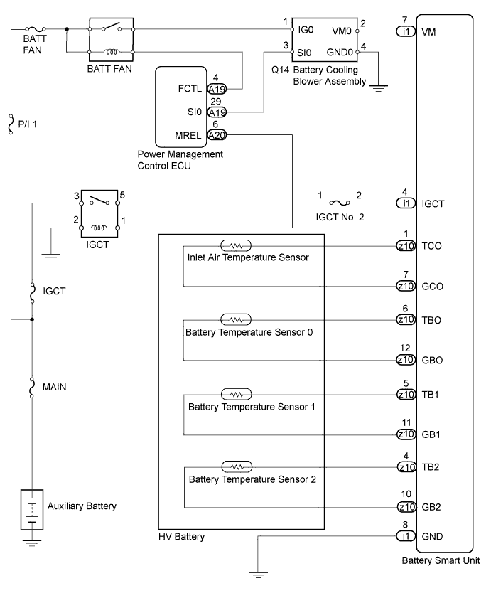
| 1.CHECK DTC OUTPUT (HV) |
Connect the intelligent tester to the DLC3.
Turn the power switch on (IG).
Enter the following menus: Powertrain / Hybrid Control / DTC.
Check if DTCs are output.
| Result | Proceed to |
| P0AFC-123 is not output. | A |
| P0AFC-123 is also output. | B |
Turn the power switch off.
|
| ||||
| A | |
 |
| 2.CHECK HARNESS AND CONNECTOR (VOLTAGE) |
Check that the service plug grip is not installed.
Connect the intelligent tester to the DLC3.
Turn the power switch on (IG).
Enter the following menus: Powertrain / Hybrid Control / Active Test / Driving the Battery Cooling Fan.
Select each air volume mode (1 to 6) in the "Driving the Battery Cooling Fan" Active Test to operate the battery cooling blower assembly.
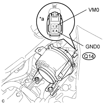 |
Measure the voltage according to the value(s) in the table below.
| Tester Connection | Condition | Specified Condition |
| Q14-2 (VM0) - Q14-4 (GND0) | Battery cooling blower is operating. | Below 5 V |
| *a | Component with harness connected (Battery Cooling Blower Assembly) |
Turn the power switch off.
|
| ||||
| OK | |
|
| 3.CHECK HV BATTERY (BATTERY TEMPERATURE SENSOR AND INLET AIR TEMPERATURE SENSOR) |
Check that the service plug grip is not installed.
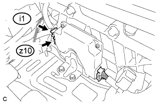 |
Disconnect connectors i1 and z10 from the battery smart unit.
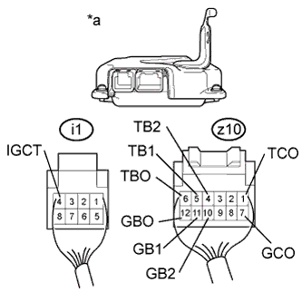 |
Measure the resistance according to the value(s) in the table below.
| Tester Connection | Switch Condition | Specified Condition |
| z10-6 (TBO) - i1-4 (IGCT) | Power switch off | 10 kΩ or higher |
| z10-12 (GBO) - i1-4 (IGCT) | Power switch off | 10 kΩ or higher |
| z10-5 (TB1) - i1-4 (IGCT) | Power switch off | 10 kΩ or higher |
| z10-11 (GB1) - i1-4 (IGCT) | Power switch off | 10 kΩ or higher |
| z10-4 (TB2) - i1-4 (IGCT) | Power switch off | 10 kΩ or higher |
| z10-10 (GB2) - i1-4 (IGCT) | Power switch off | 10 kΩ or higher |
| z10-1 (TCO) - i1-4 (IGCT) | Power switch off | 10 kΩ or higher |
| z10-7 (GCO) - i1-4 (IGCT) | Power switch off | 10 kΩ or higher |
| *a | Rear view of wire harness connector (to Battery Smart Unit) |
Connect the battery smart unit connectors.
|
| ||||
| OK | ||
 | ||
| ||
| 4.CHECK HARNESS AND CONNECTOR (INLET AIR TEMPERATURE SENSOR AND BATTERY TEMPERATURE SENSOR) |
Check that the service plug grip is not installed.
Check the wire harness and connectors of the battery temperature sensor and inlet air temperature sensor for abnormalities by sight and touch.
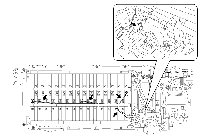
|
| ||||
| OK | ||
| ||
| ||
| 5.CHECK HARNESS AND CONNECTOR (VM0 VOLTAGE) |
Check that the service plug grip is not installed.
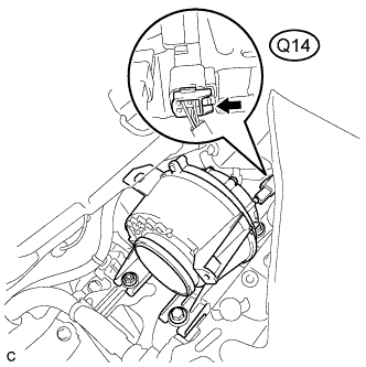 |
Disconnect connector Q14 from the battery cooling blower assembly.
Turn the power switch on (IG).
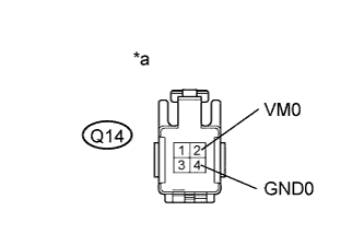 |
Measure the voltage according to the value(s) in the table below.
| Tester Connection | Switch Condition | Specified Condition |
| Q14-2 (VM0) - Q14-4 (GND0) | Power switch on (IG) | Below 5 V |
| *a | Front view of wire harness connector (to Battery Cooling Blower Assembly) |
Connect the battery cooling blower assembly connector.
|
| ||||
| OK | ||
| ||
| ||
| 6.CHECK HARNESS AND CONNECTOR (BATTERY COOLING BLOWER - BATTERY SMART UNIT) |
Check that the service plug grip is not installed.
|
Disconnect connector Q14 from the battery cooling blower assembly.
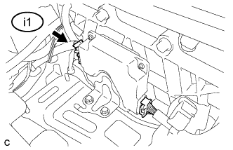 |
Disconnect connector i1 from the battery smart unit.
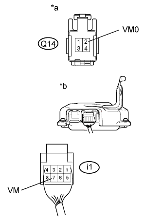 |
Measure the resistance according to the value(s) in the table below.
| Tester Connection | Switch Condition | Specified Condition |
| Q14-2 (VM0) and i1-7 (VM) - Other terminal | Power switch off | 10 kΩ or higher |
| *a | Front view of wire harness connector (to Battery Cooling Blower Assembly) |
| *b | Rear view of wire harness connector (to Battery Smart Unit) |
Connect the battery smart unit connector.
Connect the battery cooling blower assembly connector.
|
| ||||
| OK | ||
| ||
| ||


