AIR CONDITIONING SYSTEM > ECO Switch Circuit

for Preparation Click here


DESCRIPTION

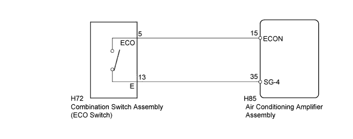
When the combination switch assembly (ECO switch) is turned on, the air conditioning amplifier assembly receives an ECO switch ON signal and controls the air conditioning to enhance fuel efficiency.
When the heater is on, the engine ON request coolant temperature will be set to a lower level. Thus, the length of time that the engine operates to generate the heat necessary to operate the heater will be limited. When the engine coolant temperature drops, the amount of air flow of the blower motor will also decrease. If FOOT/DEF or DEF is selected, or if the temperature is set to MAX HOT, the fuel efficiency control due to the combination switch assembly (ECO switch) operation will be canceled.
When the air conditioning is used to cool the vehicle, the power consumption of the compressor will be limited. Initially, the air conditioning will operate normally until the cabin temperature stabilizes. After the cabin temperature stabilizes, the power consumption of the compressor will be limited while stabilizing the cabin temperature. If the temperature is set to MAX COOL, the fuel efficiency control due to the combination switch assembly (ECO switch) operation will be canceled.

WIRING DIAGRAM


E192373E07


INSPECTION PROCEDURE

1.READ VALUE USING INTELLIGENT TESTER
  1. Connect the intelligent tester to the DLC3.

  1. Turn the power switch on (IG).

  1. Turn the intelligent tester on.

  1. Enter the following menus: Body / Air Conditioner / Data Test.

  1. Check the values by referring to the table below.

    Air Conditioner 
    Tester Display
    Measurement Item/Range
    Control Range
    Diagnostic Note
    ECO Switch
    ECO switch /
    OFF or ON
    ECO switch not operated: OFF
    (when knob is not held in ECO position)
    -
    ECO switch operated: ON
    (when knob is held in ECO position)

    OK:
    ECO switch condition displayed on the intelligent tester changes with the actual switch operation.


NG
Go to step 2
OK

PROCEED TO NEXT SUSPECTED AREA SHOWN IN PROBLEM SYMPTOMS TABLE (Click here)  

2.INSPECT COMBINATION SWITCH ASSEMBLY (ECO SWITCH)


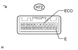
    E222437E02
  1. Measure the resistance according to the value(s) in the table below.

    Standard Resistance:
    Tester Connection
    Condition
    Specified Condition
    H72-5 (ECO) - H72-13 (E)
    ECO switch off
    (when knob is not held in ECO position)
    10 kΩ or higher
    H72-5 (ECO) - H72-13 (E)
    ECO switch on
    (when knob is held in ECO position)
    Below 1 Ω

    Text in Illustration 
    *a
    Component without harness connected
    (Combination Switch Assembly (ECO Switch))


NG
REPLACE COMBINATION SWITCH ASSEMBLY (Click here)
OK


3.CHECK HARNESS AND CONNECTOR (COMBINATION SWITCH - AIR CONDITIONING AMPLIFIER)
  1. Disconnect the H72 combination switch assembly (ECO switch) connector.

  1. Disconnect the H85 air conditioning amplifier assembly connector.

  1. Measure the resistance according to the value(s) in the table below.

    Standard Resistance:
    Tester Connection
    Condition
    Specified Condition
    H85-15 (ECON) - H72-5 (ECO)
    Always
    Below 1 Ω
    H85-15 (ECON) - Body ground
    Always
    10 kΩ or higher
    H85-35 (SG-4) - H72-13 (E)
    Always
    Below 1 Ω
    H85-35 (SG-4) - Body ground
    Always
    10 kΩ or higher


NG
REPAIR OR REPLACE HARNESS OR CONNECTOR
OK

REPLACE AIR CONDITIONING AMPLIFIER ASSEMBLY (Click here)