DTC P2532-772 Ignition Switch Run Position Circuit High |
| DTC No. | INF Code | DTC Detection Condition | Trouble Area |
| P2532 | 772 | Voltage is still applied to IG2 terminal although an IG2 relay off command is received from the power source CPU. |
|
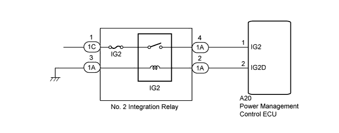
| 1.CHECK HARNESS AND CONNECTOR (+B SHORT) |
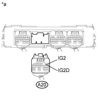 |
Disconnect connector A20 from the power management control ECU.
| *a | Rear view of wire harness connector (to Power Management Control ECU) |
Measure the voltage according to the value(s) in the table below.
| Tester Connection | Switch Condition | Specified Condition |
| A20-1 (IG2) - Body ground | Power switch off | Below 1 V |
| A20-2 (IG2D) - Body ground | Power switch off | Below 1 V |
| Result | Proceed to |
| NG | A |
| OK | B |
Connect the power management control ECU connector.
|
| ||||
| A | |
 |
| 2.CHECK HARNESS AND CONNECTOR (POWER MANAGEMENT CONTROL ECU - NO. 2 INTEGRATION RELAY) |
Disconnect connector A20 from the power management control ECU.
|
Remove the No. 2 integration relay from the engine room junction block assembly.
| *a | Rear view of wire harness connector (to Power Management Control ECU) |
Measure the voltage according to the value(s) in the table below.
| Tester Connection | Switch Condition | Specified Condition |
| A20-1 (IG2) - Body ground | Power switch off | Below 1 V |
| A20-2 (IG2D) - Body ground | Power switch off | Below 1 V |
Install the No. 2 integration relay.
Connect the power management control ECU connector.
|
| ||||
| OK | ||
 | ||
| ||

