DTC P2511-149 ECM/PCM Power Relay Sense Circuit Intermittent |
| DTC No. | INF Code | DTC Detection Condition | Trouble Area |
| P2511 | 149 | When the power switch is on (READY), the power management control ECU is reset. |
|
| 1.CHECK BATTERY TERMINAL |
Confirm whether the auxiliary battery terminals have been disconnected recently.
| Result | Proceed to |
| Terminals have been disconnected. | A |
| Terminals have not been disconnected. | B |
|
| ||||
| A | |
 |
| 2.CONFIRM THAT MASTER WARNING LIGHT ILLUMINATES |
Turn the power switch on (READY) from off.
Confirm that the master warning light illuminates.
| Result | Proceed to |
| Master warning light illuminates. | A |
| Master warning light does not illuminates. | B |
Turn the power switch off.
|
| ||||
| A | |
|
| 3.CLEAR DTC |
Connect the intelligent tester to the DLC3.
Turn the power switch on (IG).
Enter the following menus: Powertrain / Hybrid Control / DTC.
Read and record the DTCs and freeze frame data.
Clear the DTCs and freeze frame data.
Turn the power switch off.
| NEXT | |
|
| 4.CHECK DTC OUTPUT (HYBRID CONTROL) |
Connect the intelligent tester to the DLC3.
Turn the power switch on (IG).
Enter the following menus: Powertrain / Hybrid Control / DTC.
Check if DTCs are output.
| Result | Proceed to |
| DTC P2511-149 is output again. | A |
| DTCs other than P2511-149 are also output. | B |
Turn the power switch off.
|
| ||||
| A | |
|
| 5.CHECK BATTERY TERMINAL (CONTACT PROBLEM) |
Check the connection of the auxiliary battery terminals.
|
| ||||
| OK | |
|
| 6.CHECK CONNECTOR CONNECTION CONDITION (POWER MANAGEMENT CONTROL ECU CONNECTOR) |
Check the connections of the power management control ECU connectors.
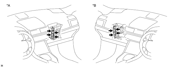
| *A | for LHD | *B | for RHD |
|
| ||||
| OK | |
|
| 7.CHECK HARNESS AND CONNECTOR (POWER MANAGEMENT CONTROL ECU - IGCT RELAY) |
Remove the IGCT relay from the engine room junction block assembly.
Disconnect connectors A19 and A20 from power management control ECU.
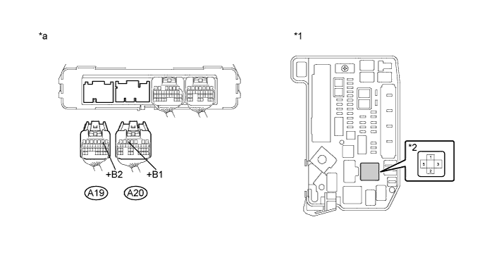
| *1 | Engine Room Junction Block Assembly | *2 | IGCT Relay |
| *a | Rear view of wire harness connector (to Power Management Control ECU) | - | - |
Measure the resistance according to the value(s) in the table below.
| Tester Connection | Switch Condition | Specified Condition |
| A20-5 (+B1) - 5 (IGCT relay) | Power switch off | Below 1 Ω |
| A19-2 (+B2) - 5 (IGCT relay) | Power switch off | Below 1 Ω |
Install the IGCT relay.
Connect the power management control ECU connector.
|
| ||||
| OK | |
|
| 8.CHECK FOR INTERMITTENT PROBLEMS |
Check for intermittent problems (Click here).
Check the connection and terminal contact pressure of connectors and wire harnesses between the power management control ECU and the engine room junction block assembly.
When the power switch is on (READY), jiggle the connectors and wire harnesses between the power management control ECU and the engine room junction block assembly.
| Result | Proceed to |
| Problem symptom does not recur. | A |
| Problem symptom recurs. | B |
|
| ||||
| A | ||
 | ||
| ||


