COMPRESSOR > INSTALLATION

for Preparation Click here


1. ADJUST COMPRESSOR OIL


    E220713
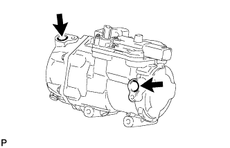
  1. When replacing the electric inverter compressor with a new one, gradually discharge the gas from the service valve of the new compressor, and drain the following amount of oil from the new electric inverter compressor before installation.

    Standard:
    (Oil capacity inside the new electric inverter compressor: 130 to 145 cc (4.4 to 4.9 fl. oz.)) - (Remaining oil amount in the removed electric inverter compressor) = (Oil amount to be removed from the new compressor when replacing)

    NOTICE:
    1. When checking the compressor oil level, observe the precautions on the air conditioning Refrigerant-Replacement.
    2. If a new compressor and magnetic clutch are installed without removing some oil, there will be too much oil in the system due to the oil remaining in the pipes of the vehicle. Excessive oil in the system prevents heat exchange in the refrigeration cycle and causes refrigeration failure.
    3. If the amount of oil remaining in the old compressor is too small, check the air conditioning system for oil leaks.
    4. Be sure to use ND-OIL 11 or equivalent for compressor oil. If any compressor oil other than ND-OIL 11 is used, compressor motor insulation performance may decrease, resulting in a leakage of electric power.


2. INSTALL ELECTRIC INVERTER COMPRESSOR
  1. Using an E8 "TORX" socket wrench, install the 2 stud bolts.

    Torque:
    10 N*m{ 102 kgf*cm , 7 ft.*lbf }

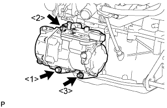
  1. Temporarily install the electric inverter compressor with the bolt and 2 nuts.


    E220716E01
  1. Install the electric inverter compressor with the bolt and 2 nuts.
    Torque:
    25 N*m{ 250 kgf*cm , 18 ft.*lbf }

    NOTICE:
    Tighten the bolts in the order shown in the illustration to install the electric inverter compressor.


    E220474E01
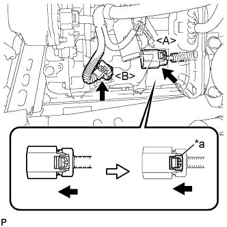
  1. Connect the connector <A> and lock the green-colored lock as shown in the illustration.

    CAUTION:
    Wear insulated gloves when performing the procedures.

    Text in Illustration 
    *a
    Green-colored Lock

  1. Connect the connector <B>.


3. CONNECT COOLER REFRIGERANT SUCTION HOSE
  1. Remove the vinyl tape from the hose.

  1. Apply a sufficient amount of compressor oil to a new O-ring and the fitting surface of the electric inverter compressor.

    Compressor oil:
    ND-OIL 11 or equivalent

  1. Install the O-ring onto the cooler refrigerant suction hose.

    NOTICE:
    1. Keep the O-ring and O-ring fitting surfaces free from dirt or foreign matter.
    2. Do not use any compressor oil other than ND-OIL 11 or equivalent. If any compressor oil other than ND-OIL 11 or equivalent is used, compressor motor insulation performance may decrease, resulting in a leakage of electric power.

  1. Install the cooler refrigerant suction hose onto the electric inverter compressor with the bolt.

    Torque:
    9.8 N*m{ 100 kgf*cm , 87 in.*lbf }


4. CONNECT COOLER REFRIGERANT DISCHARGE HOSE
  1. Remove the attached vinyl tape from the hose.

  1. Apply a sufficient amount of compressor oil to a new O-ring and the fitting surface of the electric inverter compressor.

    Compressor oil:
    ND-OIL 11 or equivalent

  1. Install the O-ring onto the cooler refrigerant discharge hose.

    NOTICE:
    1. Keep the O-ring and O-ring fitting surfaces free from dirt or foreign matter.
    2. Do not use any compressor oil other than ND-OIL 11 or equivalent. If any compressor oil other than ND-OIL 11 or equivalent is used, compressor motor insulation performance may decrease, resulting in a leakage of electric power.

  1. Install the cooler refrigerant discharge hose onto the electric inverter compressor with the bolt.

    Torque:
    9.8 N*m{ 100 kgf*cm , 87 in.*lbf }


5. CONNECT NO. 2 RADIATOR HOSE
  1. Using pliers, grip the claws of the clip and slide the clip to install the No. 2 radiator hose.


6. INSTALL SERVICE PLUG GRIP

CAUTION:
Wear insulating gloves.

NOTICE:
Before connecting the service plug, check that no parts and tools remain and that the high voltage terminals and connectors are connected securely.


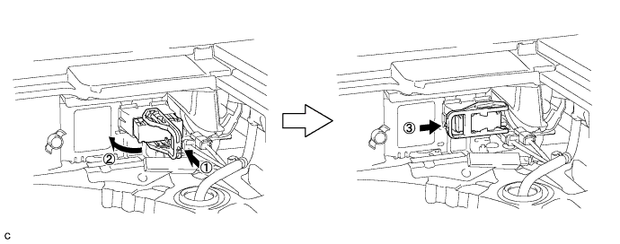
  1. Wear insulated gloves and install the service plug grip in the order shown in the illustration.

    A248487

  1. Rotate the handle of the service plug grip 90° toward the battery and slide it in the direction shown by the arrow until a click sound is heard.


7. CONNECT CABLE TO NEGATIVE BATTERY TERMINAL

NOTICE:
When disconnecting the cable, some systems need to be initialized after the cable is reconnected (Click here).


8. INSTALL REAR FLOOR BOARD UPPER NO. 3 PLATE
  1. Engage the 4 claws and 2 guides to install the rear floor board upper No. 3 plate.


9. INSTALL DECK FLOOR BOX RH
  1. Engage the 6 guides.

  1. Install the deck floor box RH with the clip.


10. INSTALL REAR NO. 3 FLOOR BOARD
  1. Install the rear No. 3 floor board.


11. INSTALL REAR DECK FLOOR BOX
  1. Install the rear deck floor box.


12. INSTALL REAR NO. 2 FLOOR BOARD
  1. Install the rear No. 2 floor board.


13. INSTALL NO. 1 ENGINE UNDER COVER


14. INSTALL INLET AIR CLEANER ASSEMBLY
  1. Install the inlet air cleaner assembly to the air cleaner case.

  1. Install the inlet air cleaner assembly with the 2 bolts and 2 clips.

    Torque:
    7.0 N*m{ 71 kgf*cm , 62 in.*lbf }

  1. Connect the wire harness clamp to the inlet air cleaner assembly.

  1. Install the water hose to the hose clamp.


15. ADD COOLANT (for Engine)
  1. Tighten the radiator drain cock plug.


    A213418E01
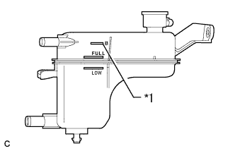
  1. Add coolant to B line of the reserve tank.
    Text in Illustration 
    *1
    B Line

    Standard Capacity:
    Item
    Capacity
    Engine coolant
    w/ Exhaust Heat Recirculation System:
    6.9 liters (7.3 US qts, 6.1 lmp. qts)
    w/o Exhaust Heat Recirculation System:
    6.5 liters (6.9 US qts, 5.7 lmp. qts)

    HINT:
    TOYOTA vehicles are filled with TOYOTA SLLC at the factory. In order to avoid damage to the engine cooling system and other technical problems, only use TOYOTA SLLC or similar high quality ethylene glycol based non-silicate, non-amine, non-nitrite, non-borate coolant with long-life hybrid organic acid technology (coolant with long-life hybrid organic acid technology is a combination of low phosphates and organic acids).

    NOTICE:
    Never use water as a substitute for engine coolant.

  1. Squeeze the radiator hoses several times by hand, and then check the level of the coolant.
    If the coolant level is low, add coolant.

  1. Put the engine in inspection mode (Click here).

  1. Install the reserve tank cap.

  1. Bleed air from the cooling system.

    NOTICE:
    1. Before starting the engine, turn the A/C switch off.
    2. Adjust the heater control to the maximum hot setting.
    3. Adjust the blower speed to the low setting.


    1. Warm up the engine until the thermostat opens. While the thermostat is open, allow the coolant to circulate for several minutes. (●1)

      HINT:
      The thermostat opening timing can be confirmed by squeezing the inlet radiator hose by hand, and sensing vibrations when the engine coolant starts to flow inside the hose.

      CAUTION:
      When squeezing the radiator hose:
      1. Wear protective gloves.
      2. Be careful as the radiator hoses are hot.
      3. Keep your hands away from the radiator fans.

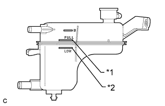
    2. Stop the engine and wait until the coolant cools down. Then if the coolant level is below the low line, add coolant so that the level will be between the full and low lines. (●2)

    3. Repeat the steps from (●1) to (●2) until the coolant level of the reserve tank remains above the low line.


    A213418E02
  1. After the engine has cooled down, check that the coolant level is between the full and low lines.
    Text in Illustration 
    *1
    Full Line
    *2
    Low Line
    If the coolant level is low, add coolant to the full line on the reserve tank.


16. INSPECT FOR COOLANT LEAK (for Engine)

CAUTION:
Do not remove the reserve tank cap while the engine and radiator are still hot. Pressurized, hot engine coolant and steam may be released and cause serious burns.

NOTICE:
Before performing each inspection, turn the A/C switch off.

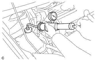
  1. Remove the reserve tank cap.


    A248150
  1. Fill the reserve tank with coolant, and then attach a radiator cap tester.

  1. Put the engine in inspection mode (Click here).

  1. Warm up the engine.

  1. Using a radiator cap tester, increase the pressure inside the radiator to 108 kPa (1.1 kgf/cm2, 16 psi), and check that the pressure does not drop. If the pressure drops, check the hoses, radiator, front exhaust pipe assembly, the heater hose around the engine coolant temperature sensor and engine water pump assembly for leaks. If no external leaks are found, check the heater core, cylinder block and cylinder head.

  1. Remove the radiator cap tester.

  1. Install the reserve tank cap.


17. CHARGE AIR CONDITIONING SYSTEM WITH REFRIGERANT
  1. Perform vacuum purging using a vacuum pump or appropriate equipment.


  1. Charge the air conditioning system with refrigerant.
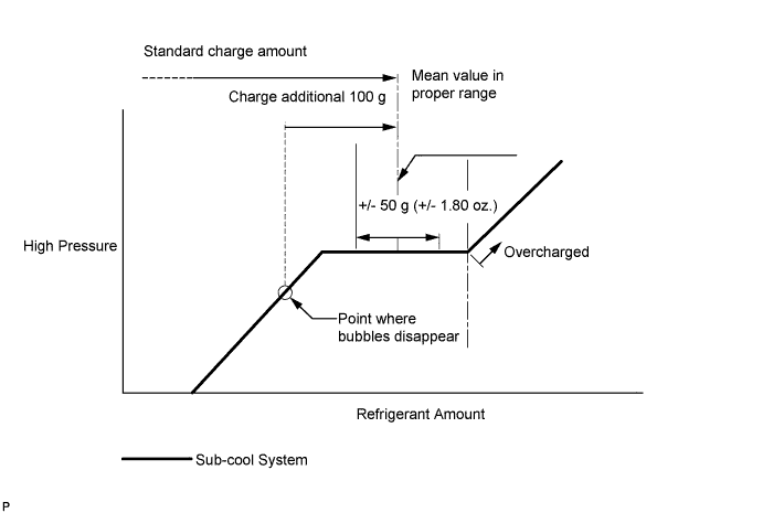
    Refrigerant type:
    HFC-134a (R134a)


    E143108E09

    Standard charge amount:
    470 g (16.6 oz.)

    SST
    09985-20010   (09985-02010, 09985-02050, 09985-02060, 09985-02070, 09985-02080, 09985-02090, 09985-02110, 09985-02130, 09985-02140, 09985-02150)

    NOTICE:
    1. Do not turn the A/C switch on before charging the air conditioning system with refrigerant. Doing so may cause the compressor to work without refrigerant, resulting in overheating of the compressor.
    2. The refrigerant amount should be checked by quantity (weight).
    3. The graph above is shown for reference only. This vehicle is not equipped with a sight glass.
    4. If at all possible, avoid using a manifold gauge set or recovery and recycling unit that has been used for vehicles with conventional compressor oil (ND-OIL 8 or equivalent). If either of these is used, conventional compressor oil remaining in the equipment will enter the air conditioning system of the vehicle, resulting in electrical insulation performance deterioration. A manifold gauge set that has been used 3 times or less can be used if an appropriate one is not available.

    HINT:
    Ensure that sufficient refrigerant is available to recharge the system when using a refrigerant recovery unit. Refrigerant recovery units are not always able to recover 100% of the refrigerant from an air conditioning system.


18. WARM UP COMPRESSOR
  1. Keep the A/C switch on for at least 2 minutes to warm up the compressor.

    NOTICE:
    To prevent damage to the compressor, be sure to warm up the compressor when turning the air conditioning on after removing and installing air conditioning system lines (including the compressor).


19. INSPECT FOR REFRIGERANT LEAK
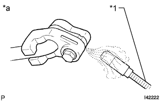
  1. After recharging the air conditioning system with refrigerant, inspect for refrigerant leaks using a halogen leak detector.

  1. Carry out the test under the following conditions:
    1. Power switch off.
    2. Secure good ventilation (the halogen leak detector may react to volatile gases which are not refrigerant, such as gasoline vapor and exhaust gas).
    3. Repeat the inspection 2 or 3 times.
    4. Measure the pressure to make sure that there is some refrigerant remaining in the air conditioning system.
      Pressure when the compressor is off: approx. 392 to 588 kPa (3.9 to 5.9 kgf/cm2, 57 to 85 psi)


    I042222E40
  1. Using a halogen leak detector, inspect for refrigerant leaks from the air conditioning system.
    Text in Illustration 
    *1
    Halogen Leak Detector
    *a
    Inspect for Leak


    N014519E08
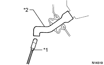
  1. Bring the halogen leak detector close to the drain hose with the detector power off, and then turn the detector on.
    Text in Illustration 
    *1
    Halogen Leak Detector
    *2
    Drain Hose

    HINT:
    1. After the blower motor has stopped, leave the cooling unit for more than 15 minutes.
    2. Bring the halogen leak detector sensor under the drain hose.
    3. When bringing the halogen leak detector close to the drain hose, make sure that the halogen leak detector does not react to volatile gases. If it is not possible to avoid interference from volatile gases, the vehicle should be lifted up to allow checking for leaks.

  1. If a refrigerant leak is not detected from the drain hose, remove the blower motor control from the cooling unit. Insert the halogen leak detector sensor into the unit and check for a leak.

  1. Disconnect the pressure sensor connector and leave it for approximately 20 minutes. Bring the halogen leak detector close to the pressure sensor and check for a leak.

    HINT:
    When checking for leaks, the presence of oily dirt at a joint can indicate a leak.