COMPRESSOR > REMOVAL

for Preparation Click here


1. PRECAUTION

NOTICE:
After turning the power switch off, waiting time may be required before disconnecting the cable from the negative (-) battery terminal. Therefore, make sure to read the disconnecting the cable from the negative (-) battery terminal notices before proceeding with work (Click here).


2. RECOVER REFRIGERANT FROM AIR CONDITIONING SYSTEM
  1. Turn the A/C switch on.

  1. Operate the air conditioning with a set temperature of 25°C (77°F) and the blower at low for 10 minutes to circulate the refrigerant. This causes most of the compressor oil from the various components of the air conditioning system to collect in the air conditioning compressor.

  1. Turn the power switch off.

  1. Recover the refrigerant from the air conditioning system using a refrigerant recovery unit.


3. REMOVE REAR NO. 2 FLOOR BOARD
  1. Remove the rear No. 2 floor board.


4. REMOVE REAR DECK FLOOR BOX
  1. Remove the rear deck floor box.


5. REMOVE REAR NO. 3 FLOOR BOARD
  1. Remove the rear No. 3 floor board.


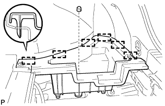
6. REMOVE DECK FLOOR BOX RH


    B270546
  1. Remove the clip.

  1. Disengage the 6 guides and remove the deck floor box RH.


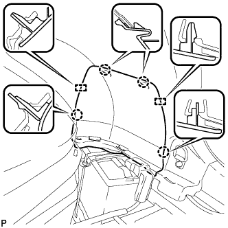
7. REMOVE REAR FLOOR BOARD UPPER NO. 3 PLATE


    B270547
  1. Disengage the 4 claws and 2 guides, and remove the rear floor board upper No. 3 plate.


8. DISCONNECT CABLE FROM NEGATIVE BATTERY TERMINAL

NOTICE:
When disconnecting the cable, some systems need to be initialized after the cable is reconnected (Click here).


9. REMOVE SERVICE PLUG GRIP

CAUTION:
  1. Wear insulating gloves.
  2. Remove the service plug grip to interrupt the high voltage circuit at the time of inspection or repair.
  3. Keep the removed service plug grip in your pocket to prevent other technicians from accidentally reconnecting it while you are servicing the vehicle.
  4. High voltage wiring connectors are orange.


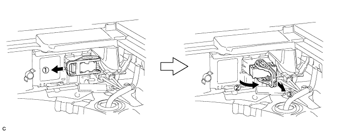
  1. Wear insulated gloves and remove the service plug grip after sliding up the lever of the service plug grip as shown in the illustration.

    A248488

    CAUTION:
    1. Keep the removed service plug grip in your pocket to prevent other technicians from accidentally reconnecting it while you are servicing the vehicle.
    2. After removing the service plug grip, do not touch the high voltage connectors or terminals for 10 minutes.

    HINT:
    Waiting for at least 10 minutes is required to discharge the high-voltage capacitor inside the inverter with converter assembly.


10. REMOVE INVERTER COVER

CAUTION:
Wear insulating gloves.


    A209686
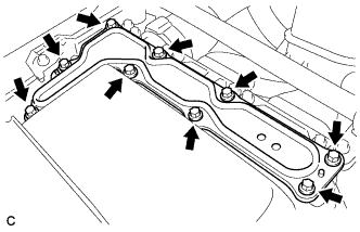
  1. Remove the 9 bolts and inverter cover.

    NOTICE:
    Make sure to pull the inverter cover straight up, as a connector is connected to the bottom of the cover.


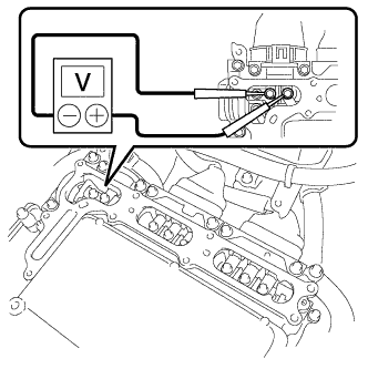
11. CHECK TERMINAL VOLTAGE

CAUTION:
Wear insulating gloves.

NOTICE:
Do not allow any foreign objects or water to enter the inverter with converter assembly.


    A248051
  1. Using a voltmeter, measure the voltage between the terminals of the 2 phase connectors.

    Standard voltage:
    0 V

    HINT:
    Use measuring range of DC 750 V or more on the voltmeter.


12. INSTALL INVERTER COVER

CAUTION:
Wear insulating gloves.

NOTICE:
  1. Make sure that the interlock is fully engaged.
  2. Do not allow any foreign objects or water to enter the inverter with converter assembly.


    A231540E01
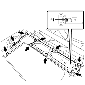
  1. Install the inverter cover with the 9 bolts to the inverter with converter assembly.
    Text in Illustration 
    *1
    Interlock

    Torque:
    11 N*m{ 112 kgf*cm , 8 ft.*lbf }


13. REMOVE INLET AIR CLEANER ASSEMBLY


    A247954
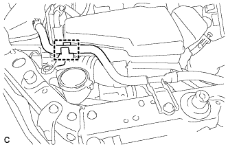
  1. Separate the water hose from the hose clamp.
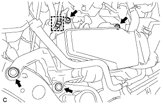


    A247955
  1. Separate the wire harness clamp from the inlet air cleaner assembly.

  1. Remove the 2 bolts, 2 clips and inlet air cleaner assembly.


14. REMOVE NO. 1 ENGINE UNDER COVER


15. DRAIN COOLANT (for Engine)

NOTICE:
Do not remove the reserve tank cap and radiator drain cock plug while the engine and radiator are still hot. Pressurized, hot engine coolant and steam may be released and cause serious burns.

  1. Loosen the radiator drain cock plug.

    HINT:
    Collect the coolant in a container and dispose of it according to the local regulations.


  1. Remove the reserve tank cap and drain the coolant.
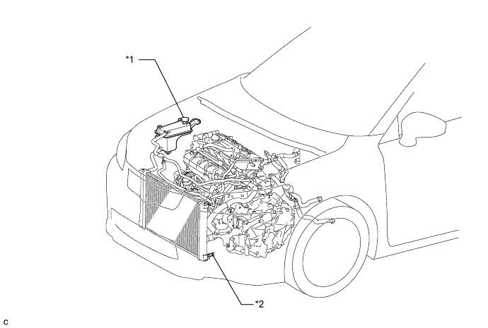

    A251091E01


    Text in Illustration 
    *1
    Reserve Tank Cap
    *2
    Radiator Drain Cock Plug


16. DISCONNECT NO. 2 RADIATOR HOSE


    E220470
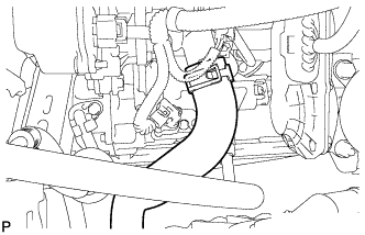
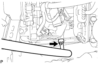
  1. Using pliers, grip the claws of the clip and slide the clip to remove the No. 2 radiator hose.


17. DISCONNECT COOLER REFRIGERANT DISCHARGE HOSE


    E220471
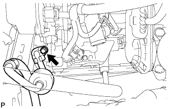
  1. Remove the bolt and disconnect the cooler refrigerant discharge hose from the electric inverter compressor.

  1. Remove the O-ring from the cooler refrigerant discharge hose.

    NOTICE:
    Seal the openings of the disconnected parts using vinyl tape to prevent entry of moisture and foreign matter.


18. DISCONNECT COOLER REFRIGERANT SUCTION HOSE


    E220472
  1. Remove the bolt and disconnect the cooler refrigerant suction hose from the electric inverter compressor.

  1. Remove the O-ring from the cooler refrigerant suction hose.

    NOTICE:
    Seal the openings of the disconnected parts using vinyl tape to prevent entry of moisture and foreign matter.


19. REMOVE ELECTRIC INVERTER COMPRESSOR


    E220473E01
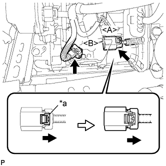
  1. Release the green-colored lock and disconnect the connector <A> as shown in the illustration.

    CAUTION:
    Wear insulated gloves when performing the procedures.

    NOTICE:
    Insulate the connector by sealing it with tape.

    Text in Illustration 
    *a
    Green-colored Lock

  1. Disconnect the connector <B>.


    E220714
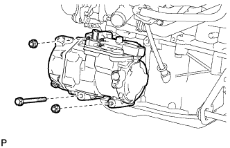
  1. Remove the bolt, 2 nuts and electric inverter compressor.
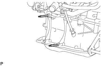


    E220715
  1. Using an E8 "TORX" socket wrench, remove the 2 stud bolts.