DTC U1002 Lost Communication with Gateway Module (Power Management1) |
| DTC No. | DTC Detection Condition | Trouble Area |
| U1002 | Power management control ECU cannot receive signals from all ECUs that have been memorized as those connected to the V2 bus. |
|
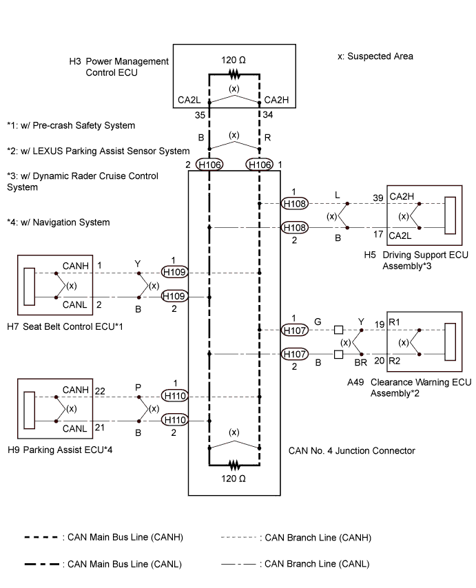
| 1.CHECK V2 BUS LINES |
Turn the power switch off.
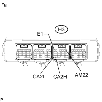 |
Measure the resistance according to the value(s) in the table below.
| Tester Connection | Switch Condition | Specified Condition | Result |
| H3-34 (CA2H) - H3-35 (CA2L) | Power switch off | 54 to 69 Ω | Below 54 Ω: Short circuit between bus lines |
| 70 Ω or higher: Open circuit in a main bus line | |||
| H3-34 (CA2H) - H3-6 (E1) | Power switch off | 200 Ω or higher | Below 200 Ω: CANH ground short |
| H3-35 (CA2L) - H3-6 (E1) | Power switch off | 200 Ω or higher | Below 200 Ω: CANL ground short |
| *a | Component with harness connected (Power Management Control ECU) |
Disconnect the cable from the negative (-) auxiliary battery terminal.
Measure the resistance according to the value(s) in the table below.
| Tester Connection | Condition | Specified Condition | Result |
| H3-34 (CA2H) - H3-1 (AM22) | Cable disconnected from negative (-) auxiliary battery terminal | 6 kΩ or higher | Below 6 kΩ: CANH +B short |
| H3-35 (CA2L) - H3-1 (AM22) | Cable disconnected from negative (-) auxiliary battery terminal | 6 kΩ or higher | Below 6 kΩ: CANL +B short |
| Result | Proceed to |
| OK | A |
| Open circuit in CAN main bus line | B |
| Short circuit between bus lines | C |
| D |
|
| ||||
|
| ||||
|
| ||||
| A | |
 |
| 2.CHECK DTC OUTPUT |
Clear the DTCs.
Turn the power switch off.
Turn the power switch on (IG) and recheck for DTCs.
| Result | Proceed to |
| U1002 is output from power management control ECU (Intelligent tester display/ PM1 Gateway) | A |
| Other DTC is output | B |
|
| ||||
| A | ||
 | ||
| ||
| 3.CHECK FOR OPEN IN V2 BUS MAIN LINES (POWER MANAGEMENT CONTROL ECU MAIN WIRE) |
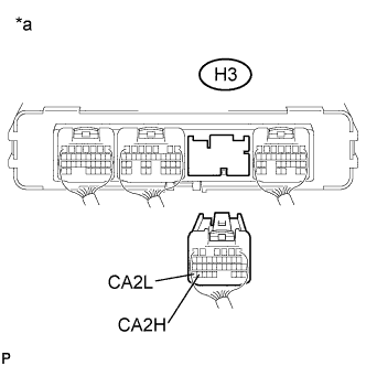 |
Disconnect the power management control ECU connector.
Measure the resistance according to the value(s) in the table below.
| Tester Connection | Switch Condition | Specified Condition |
| H3-34 (CA2H) - H3-35 (CA2L) | Power switch off | 108 to 132 Ω |
| *a | Rear view of wire harness connector (to Power Management Control ECU) |
|
| ||||
| OK | ||
| ||
| ||
| 4.CHECK FOR OPEN IN V2 BUS MAIN LINES (CAN NO. 4 J/C - POWER MANAGEMENT CONTROL ECU) |
Reconnect the power management control ECU connector.
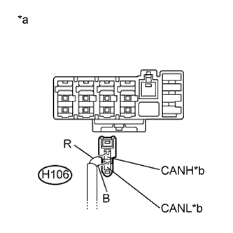 |
Disconnect the power management control ECU main line connector from the CAN No. 4 junction connector.
Measure the resistance according to the value(s) in the table below.
| Tester Connection | Switch Condition | Specified Condition | Connected to |
| H106-1 (CANH) - H106-2 (CANL) | Power switch off | 108 to 132 Ω | Power management control ECU |
| *a | Rear view of wire harness connector (to CAN No. 4 Junction Connector) |
| *b | to Power Management Control ECU |
|
| ||||
| OK | ||
| ||
| ||
| 5.CHECK FOR SHORT IN V2 BUS LINES (POWER MANAGEMENT CONTROL ECU) |
|
Disconnect the power management control ECU connector.
Measure the resistance according to the value(s) in the table below.
| Tester Connection | Switch Condition | Specified Condition |
| H3-34 (CA2H) - H3-35 (CA2L) | Power switch off | 108 to 132 Ω |
| *a | Rear view of wire harness connector (to Power Management Control ECU) |
|
| ||||
| OK | ||
| ||
| ||
| 6.CHECK FOR SHORT IN V2 BUS LINES (CAN NO. 4 J/C - POWER MANAGEMENT CONTROL ECU) |
Reconnect the power management control ECU connector.
|
Disconnect the power management control ECU main line connector from the CAN No. 4 junction connector.
Measure the resistance according to the value(s) in the table below.
| Tester Connection | Switch Condition | Specified Condition | Connected to |
| H106-1 (CANH) - H106-2 (CANL) | Power switch off | 108 to 132 Ω | Power management control ECU |
| *a | Rear view of wire harness connector (to CAN No. 4 Junction Connector) |
| *b | to Power Management Control ECU |
|
| ||||
| OK | |
|
| 7.CHECK FOR SHORT IN V2 BUS LINES (CAN NO. 4 J/C) |
Reconnect the power management control ECU main line connector to the CAN No. 4 junction connector.
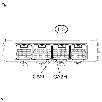 |
Connect the probes of an ohmmeter to terminals 34 (CA2H) and 35 (CA2L) of the power management control ECU.
| *a | Component with harness connector (Power Management Control ECU) |
While observing the resistance value shown on the ohmmeter, disconnect branch line connectors (except H106) from the CAN No. 4 junction connector until the resistance becomes normal (between 54 and 69 Ω).
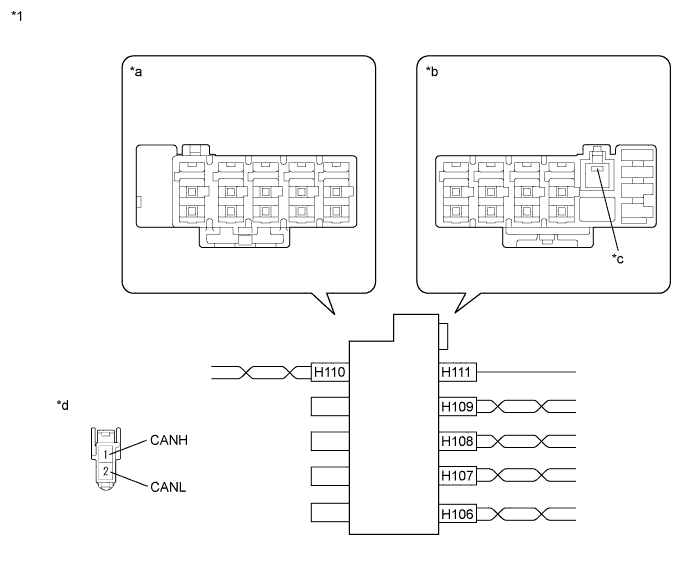
| *1 | CAN No. 4 Junction Connector | - | - |
| *a | Junction Connector B Side | *b | Junction Connector A Side |
| *c | Earth Terminal | *d | Front view of wire harness connector (to CAN No. 4 Junction Connector) |
| Terminal No. (Symbol) | Wiring Color | Connected to |
| H110-1 (CANH) | P | Parking assist ECU |
| H110-2 (CANL) | B |
| Terminal No. (Symbol) | Wiring Color | Connected to |
| H111-1 (GND) | W-B | Body ground |
| H106-1 (CANH) | R | Power management control ECU |
| H106-2 (CANL) | B | |
| H107-1 (CANH) | G | Clearance warning ECU assembly |
| H107-2 (CANL) | B | |
| H108-1 (CANH) | L | Driving support ECU assembly |
| H108-2 (CANL) | B | |
| H109-1 (CANH) | Y | Seat belt control ECU |
| H109-2 (CANL) | B |
| Result | Proceed to |
| The resistance is still below 54 Ω when all the specified connectors are disconnected. (There is no short in the branch lines.) | A |
| The resistance becomes normal (between 54 and 69 Ω) when a connector is disconnected. (There is a short in one or more of the branch lines.) | B |
|
| ||||
| A | ||
| ||
| ||
| 8.CHECK FOR SHORT IN V2 BUS LINES (ECUS) |
Reconnect the connector for the short-circuited branch line to the CAN junction connector (the connector that caused the bus line resistance to become normal (between 54 and 69 Ω) when it was disconnected).
Disconnect the connector that includes terminals CANH and CANL from the ECU to which the short-circuited branch line is connected.
|
Measure the resistance according to the value(s) in the table below.
| Tester Connection | Switch Condition | Specified Condition |
| H3-34 (CA2H) - H3-35 (CA2L) | Power switch off | 54 to 69 Ω |
| *a | Component with harness connector (Power Management Control ECU) |
|
| ||||
| OK | ||
| ||
| ||
| 9.CHECK FOR SHORT IN V2 BUS LINE (POWER MANAGEMENT CONTROL ECU) |
 |
Disconnect the power management control ECU connector.
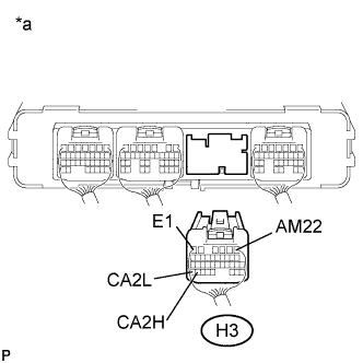
Measure the resistance according to the value(s) in the table below.
| Tester Connection | Condition | Specified Condition | Purpose |
| H3-34 (CA2H) - H3-6 (E1) | Power switch off | 200 Ω or higher | Inspection for CANH ground short |
| H3-35 (CA2L) - H3-6 (E1) | Power switch off | 200 Ω or higher | Inspection for CANL ground short |
| H3-34 (CA2H) - H3-1 (AM22) | Cable disconnected from negative (-) auxiliary battery terminal | 6 kΩ or higher | Inspection for CANH +B short |
| H3-35 (CA2L) - H3-1 (AM22) | Cable disconnected from negative (-) auxiliary battery terminal | 6 kΩ or higher | Inspection for CANL +B short |
| *a | Rear view of wire harness connector (to Power Management Control ECU) |
|
| ||||
| OK | ||
| ||
| ||
| 10.CHECK FOR SHORT IN V2 BUS LINE (CAN NO. 4 J/C - POWER MANAGEMENT CONTROL ECU) |
|
Disconnect the power management control ECU main line connector from the CAN No. 4 junction connector.
| *a | Rear view of wire harness connector (to CAN No. 4 Junction Connector) |
| *b | to Power Management Control ECU |
|
Measure the resistance according to the value(s) in the table below.
| Tester Connection | Condition | Specified Condition | Purpose |
| H3-34 (CA2H) - H3-6 (E1) | Power switch off | 200 Ω or higher | Inspection for CANH ground short |
| H3-35 (CA2L) - H3-6 (E1) | Power switch off | 200 Ω or higher | Inspection for CANL ground short |
| H3-34 (CA2H) - H3-1 (AM22) | Cable disconnected from negative (-) auxiliary battery terminal | 6 kΩ or higher | Inspection for CANH +B short |
| H3-35 (CA2L) - H3-1 (AM22) | Cable disconnected from negative (-) auxiliary battery terminal | 6 kΩ or higher | Inspection for CANL +B short |
| *a | Rear view of wire harness connector (to Power Management Control ECU) |
|
| ||||
| OK | |
|
| 11.CHECK FOR SHORT IN V2 BUS LINE (CAN NO. 4 J/C) |
Reconnect the power management control ECU main line connector to the CAN No. 4 junction connector.
|
Connect the probes of an ohmmeter to terminals CANH or CANL and GND or +B (AM22) of the power management control ECU.
| *a | Rear view of wire harness connector (to Power Management Control ECU) |
While observing the resistance value shown on the ohmmeter, disconnect branch line connectors (except H106) from the CAN No. 4 junction connector until the resistance becomes normal (6 kΩ or higher (for +B short) or 200 Ω or higher (for ground short)).
| *1 | CAN No. 4 Junction Connector | - | - |
| *a | Junction Connector B Side | *b | Junction Connector A Side |
| *c | Earth Terminal | *d | Front view of wire harness connector (to CAN No. 4 Junction Connector) |
| Terminal No. (Symbol) | Wiring Color | Connected to |
| H110-1 (CANH) | P | Parking assist ECU |
| H110-2 (CANL) | B |
| Terminal No. (Symbol) | Wiring Color | Connected to |
| H111-1 (GND) | W-B | Body ground |
| H106-1 (CANH) | R | Power management control ECU |
| H106-2 (CANL) | B | |
| H107-1 (CANH) | G | Clearance warning ECU assembly |
| H107-2 (CANL) | B | |
| H108-1 (CANH) | L | Driving support ECU assembly |
| H108-2 (CANL) | B | |
| H109-1 (CANH) | Y | Seat belt control ECU |
| H109-2 (CANL) | B |
| Result | Proceed to |
| The resistance between terminals CANH and BAT, or the resistance between terminals CANL and BAT is still below 6 kΩ when all the specified connectors are disconnected from the CAN junction connector. (There is no short to +B in the branch lines.) | A |
| The resistance between terminals CANH and GND, or the resistance between terminals CANL and GND is still below 200 Ω when all the specified connectors are disconnected from the CAN junction connector. (There is no short to GND in the branch lines.) | |
| The resistance between terminals CANH and BAT, or the resistance between terminals CANL and BAT becomes normal (6 kΩ or higher) when a connector is disconnected from the CAN junction connector. (There is a short to +B in one of the areas related to one or more of the disconnected branch lines.) | B |
| The resistance between terminals CANH and GND, or the resistance between terminals CANL and GND becomes normal (200 Ω or higher) when a connector is disconnected from the CAN junction connector. (There is a short to GND in one of the areas related to one or more of the disconnected branch lines.) |
|
| ||||
| A | ||
| ||
| ||
| 12.CHECK FOR SHORT IN V2 BUS LINE (ECUS) |
Reconnect the connector for the bus line that is shorted to +B or GND to the CAN junction connector (the connector that caused the bus line resistance to change to 6 kΩ or higher (for +B short) or 200 Ω or higher (for ground short) when it was disconnected).
Disconnect the connector that includes terminals CANH and CANL from the ECU to which the bus line shorted to +B or GND is connected.
|
Measure the resistance according to the value(s) in the table below.
| Tester Connection | Condition | Specified Condition | Purpose |
| H3-34 (CA2H) - H3-6 (E1) | Power switch off | 200 Ω or higher | Inspection for CANH ground short |
| H3-35 (CA2L) - H3-6 (E1) | Power switch off | 200 Ω or higher | Inspection for CANL ground short |
| H3-34 (CA2H) - H3-1 (AM22) | Cable disconnected from negative (-) auxiliary battery terminal | 6 kΩ or higher | Inspection for CANH +B short |
| H3-35 (CA2L) - H3-1 (AM22) | Cable disconnected from negative (-) auxiliary battery terminal | 6 kΩ or higher | Inspection for CANL +B short |
| *a | Rear view of wire harness connector (to Power Management Control ECU) |
|
| ||||
| OK | ||
| ||
| ||


