DTC U1002 Lost Communication with Gateway Module (Power Management2) |
| DTC No. | DTC Detection Condition | Trouble Area |
| U1002 | Power management control ECU cannot receive signals from all ECUs that have been memorized as those connected to the power management bus. |
|
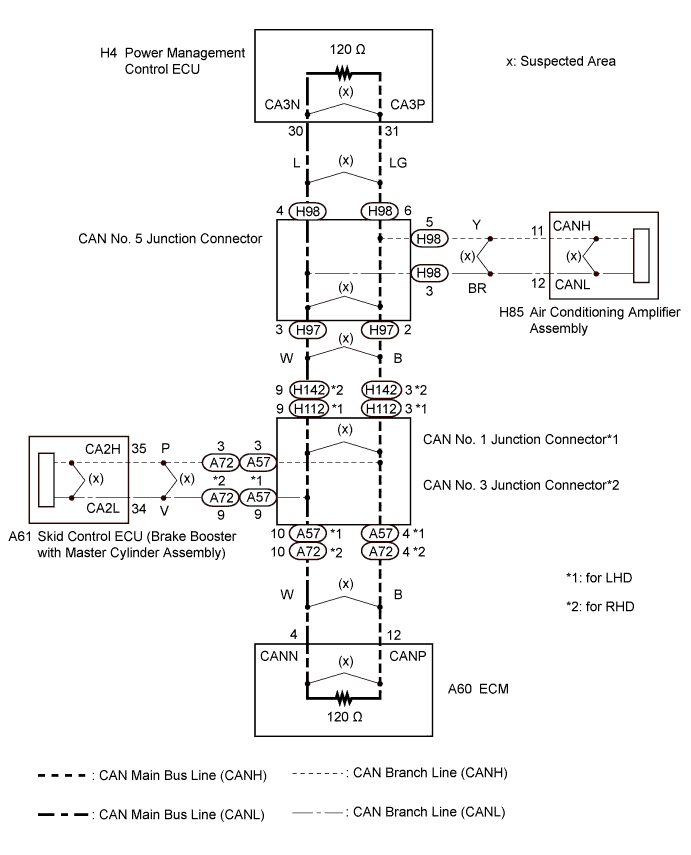
| 1.CHECK CAN BUS LINES |
Turn the power switch off.
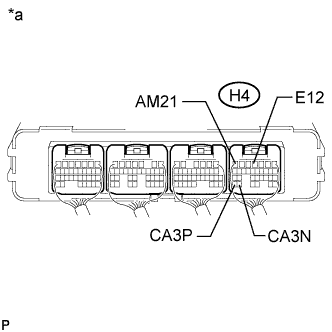 |
Measure the resistance according to the value(s) in the table below.
| Tester Connection | Switch Condition | Specified Condition | Result |
| H4-31 (CA3P) - H4-30 (CA3N) | Power switch off | 54 to 69 Ω | Below 54 Ω: Short circuit between bus lines |
| 70 Ω or higher: Open circuit in a main bus line | |||
| H4-31 (CA3P) - H4-4 (E12) | Power switch off | 200 Ω or higher | Below 200 Ω: CANH ground short |
| H4-30 (CA3N) - H4-4 (E12) | Power switch off | 200 Ω or higher | Below 200 Ω: CANL ground short |
Disconnect the cable from the negative (-) auxiliary battery terminal.
Measure the resistance according to the value(s) in the table below.
| Tester Connection | Condition | Specified Condition | Result |
| H4-31 (CA3P) - H4-7 (AM21) | Cable disconnected from negative (-) auxiliary battery terminal | 6 kΩ or higher | Below 6 kΩ: CANH +B short |
| H4-30 (CA3N) - H4-7 (AM21) | Cable disconnected from negative (-) auxiliary battery terminal | 6 kΩ or higher | Below 6 kΩ: CANL +B short |
| *a | Component with harness connector (Power Management Control ECU) |
| Result | Proceed to |
| OK | A |
| Open circuit in CAN main bus line | B |
| Short circuit between bus lines | C |
| D |
|
| ||||
|
| ||||
|
| ||||
| A | |
 |
| 2.CHECK FOR DTC OUTPUT |
Clear the DTCs.
Turn the power switch off.
Turn the power switch on (IG) and recheck for DTCs.
| Result | Proceed to |
| U1002 is output from power management control ECU (Intelligent tester display/PM2 Gateway) | A |
| Other DTC is output | B |
|
| ||||
| A | ||
 | ||
| ||
| 3.CHECK FOR OPEN IN CAN BUS LINES (POWER MANAGEMENT CONTROL ECU) |
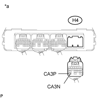 |
Disconnect the power management control ECU connector.
Measure the resistance according to the value(s) in the table below.
| Tester Connection | Switch Condition | Specified Condition |
| H4-31 (CA3P) - H4-30 (CA3N) | Power switch off | 108 to 132 Ω |
| *a | Rear view of wire harness connector (to Power Management Control ECU) |
| Result | Proceed to |
| OK | A |
| NG (for LHD) | B |
| NG (for RHD) | C |
|
| ||||
|
| ||||
| A | ||
| ||
| ||
| 4.CHECK FOR OPEN IN CAN BUS LINES (CAN NO. 5 J/C - CAN NO. 1 J/C) |
Reconnect the power management control ECU connector.
Disconnect the wire harness connector from CAN No. 5 junction connector front side.
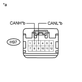 |
Measure the resistance according to the value(s) in the table below.
| Tester Connection | Switch Condition | Specified Condition |
| H97-2 (CANH) - H97-3 (CANL) | Power switch off | 108 to 132 Ω |
| *a | Front view of wire harness connector (to CAN No. 5 Junction Connector) |
| *b | to CAN No. 1 Junction Connector |
|
| ||||
| OK | |
|
| 5.CHECK FOR OPEN IN CAN BUS LINES (CAN NO. 5 J/C - POWER MANAGEMENT CONTROL ECU) |
Reconnect the wire harness connector to the CAN No. 5 junction connector front side.
Disconnect the wire harness connector from the CAN No. 5 junction connector rear side.
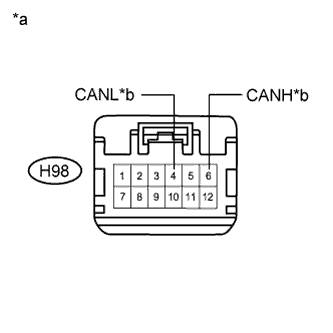 |
Measure the resistance according to the value(s) in the table below.
| Tester Connection | Switch Condition | Specified Condition |
| H98-6 (CANH) - H98-4 (CANL) | Power switch off | 108 to 132 Ω |
| *a | Front view of wire harness connector (to CAN No. 5 Junction Connector) |
| *b | to Power Management Control ECU |
|
| ||||
| OK | ||
| ||
| ||
| 6.CHECK FOR OPEN IN CAN BUS LINES (CAN NO. 1 J/C - CAN NO. 5 J/C) |
Reconnect the wire harness connector to the CAN No. 5 junction connector rear side.
Disconnect the instrument panel wire from the CAN No. 1 junction connector.
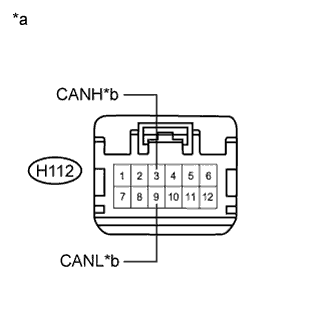 |
Measure the resistance according to the value(s) in the table below.
| Tester Connection | Switch Condition | Specified Condition |
| H112-3 (CANH) - H112-9 (CANL) | Power switch off | 108 to 132 Ω |
| *a | Front view of wire harness connector (to CAN No. 1 Junction Connector) |
| *b | to CAN No. 5 Junction Connector |
|
| ||||
| OK | |
|
| 7.CHECK FOR OPEN IN CAN BUS LINES (CAN NO. 1 J/C - ECM) |
Reconnect the instrument panel wire to the CAN No. 1 junction connector.
Disconnect the engine room main wire from the CAN No. 1 junction connector.
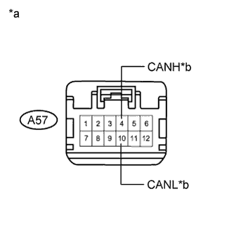 |
Measure the resistance according to the value(s) in the table below.
| Tester Connection | Switch Condition | Specified Condition |
| A57-4 (CANH) - A57-10 (CANL) | Power switch off | 108 to 132 Ω |
| *a | Front view of wire harness connector (to CAN No. 1 Junction Connector) |
| *b | to ECM |
|
| ||||
| OK | ||
| ||
| ||
| 8.CHECK FOR OPEN IN CAN BUS LINES (ECM) |
Reconnect the engine room main wire to the CAN No. 1 junction connector.
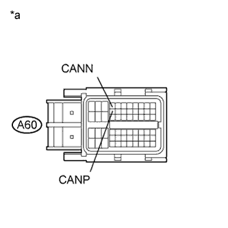 |
Disconnect the ECM connector.
Measure the resistance according to the value(s) in the table below.
| Tester Connection | Switch Condition | Specified Condition |
| A60-12 (CANP) - A60-4 (CANN) | Power switch off | 108 to 132 Ω |
| *a | Front view of wire harness connector (to ECM) |
|
| ||||
| OK | ||
| ||
| ||
| 9.CHECK FOR OPEN IN CAN BUS LINES (CAN NO. 5 J/C - CAN NO. 3 J/C) |
Reconnect the power management control ECU connector.
Disconnect the wire harness connector from CAN No. 5 junction connector front side.
|
Measure the resistance according to the value(s) in the table below.
| Tester Connection | Switch Condition | Specified Condition |
| H97-2 (CANH) - H97-3 (CANL) | Power switch off | 108 to 132 Ω |
| *a | Front view of wire harness connector (to CAN No. 5 Junction Connector) |
| *b | to CAN No. 3 Junction Connector |
|
| ||||
| OK | |
|
| 10.CHECK FOR OPEN IN CAN BUS LINES (CAN NO. 5 J/C - POWER MANAGEMENT CONTROL ECU) |
Reconnect the wire harness connector to the CAN No. 5 junction connector front side.
Disconnect the wire harness connector from the CAN No. 5 junction connector rear side.
|
Measure the resistance according to the value(s) in the table below.
| Tester Connection | Switch Condition | Specified Condition |
| H98-6 (CANH) - H98-4 (CANL) | Power switch off | 108 to 132 Ω |
| *a | Front view of wire harness connector (to CAN No. 5 Junction Connector) |
| *b | to Power Management Control ECU |
|
| ||||
| OK | ||
| ||
| ||
| 11.CHECK FOR OPEN IN CAN BUS LINES (CAN NO. 3 J/C - CAN NO. 5 J/C) |
Reconnect the wire harness connector to the CAN No. 5 junction connector rear side.
Disconnect the instrument panel wire from the CAN No. 3 junction connector.
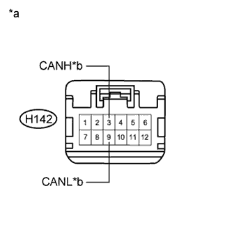 |
Measure the resistance according to the value(s) in the table below.
| Tester Connection | Switch Condition | Specified Condition |
| H142-3 (CANH) - H142-9 (CANL) | Power switch off | 108 to 132 Ω |
| *a | Front view of wire harness connector (to CAN No. 3 Junction Connector) |
| *b | to CAN No. 5 Junction Connector |
|
| ||||
| OK | |
|
| 12.CHECK FOR OPEN IN CAN BUS LINE (CAN NO. 3 J/C - ECM) |
Reconnect the instrument panel wire to the CAN No. 3 junction connector.
Disconnect the engine room main wire from the CAN No. 3 junction connector.
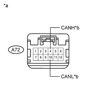 |
Measure the resistance according to the value(s) in the table below.
| Tester Connection | Switch Condition | Specified Condition |
| A72-4 (CANH) - A72-10 (CANL) | Power switch off | 108 to 132 Ω |
| *a | Front view of wire harness connector (to CAN No. 3 Junction Connector) |
| *b | to ECM |
|
| ||||
| OK | ||
| ||
| ||
| 13.CHECK FOR OPEN IN CAN BUS LINES (ECM) |
Reconnect the engine room main wire to the CAN No. 3 junction connector.
|
Disconnect the ECM connector.
Measure the resistance according to the value(s) in the table below.
| Tester Connection | Switch Condition | Specified Condition |
| A60-12 (CANP) - A60-4 (CANN) | Power switch off | 108 to 132 Ω |
| *a | Front view of wire harness connector (to ECM) |
|
| ||||
| OK | ||
| ||
| ||
| 14.CHECK FOR SHORT IN CAN BUS LINES (POWER MANAGEMENT CONTROL ECU) |
|
Disconnect the power management control ECU connector.
Measure the resistance according to the value(s) in the table below.
| Tester Connection | Switch Condition | Specified Condition |
| H4-31 (CA3P) - H4-30 (CA3N) | Power switch off | 108 to 132 Ω |
| *a | Rear view of wire harness connector (to Power Management Control ECU) |
|
| ||||
| OK | ||
| ||
| ||
| 15.CHECK FOR SHORT IN CAN BUS LINES (CAN NO. 5 J/C - POWER MANAGEMENT CONTROL ECU) |
Reconnect the power management control ECU connector.
Disconnect the wire harness connector from the CAN No. 5 junction connector rear side.
|
Measure the resistance according to the value(s) in the table below.
| Tester Connection | Switch Condition | Specified Condition |
| H98-6 (CANH) - H98-4 (CANL) | Power switch off | 108 to 132 Ω |
| *a | Front view of wire harness connector (to CAN No. 5 Junction Connector) |
| *b | to Power Management Control ECU |
| Result | Proceed to |
| OK (for LHD) | A |
| OK (for RHD) | B |
| NG | C |
|
| ||||
|
| ||||
| A | |
|
| 16.CHECK FOR SHORT IN CAN BUS LINES (CAN NO. 5 J/C - CAN NO. 1 J/C) |
Disconnect the wire harness connector from CAN No. 5 junction connector front side.
|
Measure the resistance according to the value(s) in the table below.
| Tester Connection | Switch Condition | Specified Condition |
| H97-2 (CANH) - H97-3 (CANL) | Power switch off | 108 to 132 Ω |
| *a | Front view of wire harness connector (to CAN No. 5 Junction Connector) |
| *b | to CAN No. 1 Junction Connector |
|
| ||||
| OK | |
|
| 17.CHECK FOR SHORT IN CAN BUS LINES (CAN NO. 5 J/C - AIR CONDITIONING AMPLIFIER ASSEMBLY) |
Disconnect the air conditioning amplifier assembly connector.
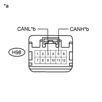 |
Measure the resistance according to the value(s) in the table below.
| Tester Connection | Switch Condition | Specified Condition |
| H98-5 (CANH) - H98-3 (CANL) | Power switch off | 1 MΩ or higher |
| *a | Front view of wire harness connector (to CAN No. 5 Junction Connector) |
| *b | to Air Conditioning Amplifier Assembly |
|
| ||||
| OK | |
|
| 18.CHECK FOR SHORT IN CAN BUS LINES (AIR CONDITIONING AMPLIFIER ASSEMBLY) |
Reconnect the wire harness connector to the CAN No. 5 junction connector front side and rear side.
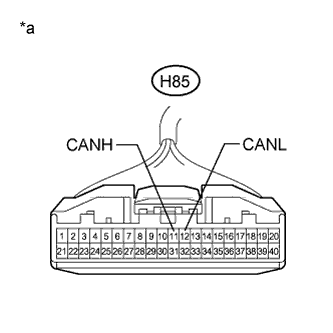 |
Measure the resistance according to the value(s) in the table below.
| Tester Connection | Switch Condition | Specified Condition |
| H85-11 (CANH) - H85-12 (CANL) | Power switch off | 54 to 69 Ω |
| *a | Front view of wire harness connector (to Air Conditioning Amplifier Assembly) |
|
| ||||
| OK | ||
| ||
| ||
| 19.CHECK FOR SHORT IN CAN BUS LINES (CAN NO. 1 J/C - CAN NO. 5 J/C) |
Reconnect the wire harness connector to the CAN No. 5 junction connector front side and rear side.
Disconnect the instrument panel wire from the CAN No. 1 junction connector.
|
Measure the resistance according to the value(s) in the table below.
| Tester Connection | Switch Condition | Specified Condition |
| H112-3 (CANH) - H112-9 (CANL) | Power switch off | 108 to 132 Ω |
| *a | Front view of wire harness connector (to CAN No. 1 Junction Connector) |
| *b | to CAN No. 5 Junction Connector |
|
| ||||
| OK | |
|
| 20.CHECK FOR SHORT IN CAN BUS LINES (CAN NO. 1 J/C - ECM) |
Disconnect the engine room main wire from the CAN No. 1 junction connector.
|
Measure the resistance according to the value(s) in the table below.
| Tester Connection | Switch Condition | Specified Condition |
| A57-4 (CANH) - A57-10 (CANL) | Power switch off | 108 to 132 Ω |
| *a | Front view of wire harness connector (to CAN No. 1 Junction Connector) |
| *b | to ECM |
|
| ||||
| OK | |
|
| 21.CHECK FOR SHORT IN CAN BUS LINES (CAN NO. 1 J/C - SKID CONTROL ECU) |
Disconnect the skid control ECU (brake booster with master cylinder assembly) connector.
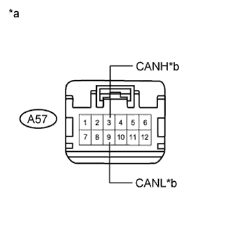 |
Measure the resistance according to the value(s) in the table below.
| Tester Connection | Switch Condition | Specified Condition |
| A57-3 (CANH) - A57-9 (CANL) | Power switch off | 1 MΩ or higher |
| *a | Front view of wire harness connector (to CAN No. 1 Junction Connector) |
| *b | to Skid Control ECU |
|
| ||||
| OK | |
|
| 22.CHECK FOR SHORT IN CAN BUS LINES (SKID CONTROL ECU) |
Reconnect the instrument panel wire and engine room main wire to the CAN No. 1 junction connector.
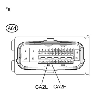 |
Measure the resistance according to the value(s) in the table below.
| Tester Connection | Switch Condition | Specified Condition |
| A61-35 (CA2H) - A61-34 (CA2L) | Power switch off | 54 to 69 Ω |
| *a | Front view of wire harness connector (to Skid Control ECU) |
| Result | Proceed to |
| OK (for LHD) | A |
| OK (for RHD) | B |
| NG | C |
|
| ||||
|
| ||||
| A | ||
| ||
| ||
| 23.CHECK FOR SHORT IN CAN BUS LINES (ECM) |
Reconnect the instrument panel wire and engine room main wire to the CAN No. 1 junction connector.
|
Disconnect the ECM connector.
Measure the resistance according to the value(s) in the table below.
| Tester Connection | Switch Condition | Specified Condition |
| A60-12 (CANP) - A60-4 (CANN) | Power switch off | 108 to 132 Ω |
| *a | Front view of wire harness connector (to ECM) |
|
| ||||
| OK | ||
| ||
| ||
| 24.CHECK FOR SHORT IN CAN BUS LINES (CAN NO. 5 J/C - CAN NO. 3 J/C) |
Disconnect the wire harness connector from CAN No. 5 junction connector front side.
|
Measure the resistance according to the value(s) in the table below.
| Tester Connection | Switch Condition | Specified Condition |
| H97-2 (CANH) - H97-3 (CANL) | Power switch off | 108 to 132 Ω |
| *a | Front view of wire harness connector (to CAN No. 5 Junction Connector) |
| *b | to CAN No. 3 Junction Connector |
|
| ||||
| OK | |
|
| 25.CHECK FOR SHORT IN CAN BUS LINES (CAN NO. 5 J/C - AIR CONDITIONING AMPLIFIER ASSEMBLY) |
Disconnect the air conditioning amplifier assembly connector.
|
Measure the resistance according to the value(s) in the table below.
| Tester Connection | Switch Condition | Specified Condition |
| H98-5 (CANH) - H98-3 (CANL) | Power switch off | 1 MΩ or higher |
| *a | Front view of wire harness connector (to CAN No. 5 Junction Connector) |
| *b | to Air Conditioning Amplifier Assembly |
|
| ||||
| OK | |
|
| 26.CHECK FOR SHORT IN CAN BUS LINES (AIR CONDITIONING AMPLIFIER ASSEMBLY) |
Reconnect the wire harness connector to the CAN No. 5 junction connector front side and rear side.
|
Measure the resistance according to the value(s) in the table below.
| Tester Connection | Switch Condition | Specified Condition |
| H85-11 (CANH) - H85-12 (CANL) | Power switch off | 54 to 69 Ω |
| *a | Front view of wire harness connector (to Air Conditioning Amplifier Assembly) |
|
| ||||
| OK | ||
| ||
| ||
| 27.CHECK FOR SHORT IN CAN BUS LINES (CAN NO. 3 J/C - CAN NO. 5 J/C) |
Reconnect the wire harness connector to the CAN No. 5 junction connector front side and rear side.
Disconnect the instrument panel wire from the CAN No. 3 junction connector.
|
Measure the resistance according to the value(s) in the table below.
| Tester Connection | Switch Condition | Specified Condition |
| H142-3 (CANH) - H142-9 (CANL) | Power switch off | 108 to 132 Ω |
| *a | Front view of wire harness connector (to CAN No. 3 Junction Connector) |
| *b | to CAN No. 5 Junction Connector |
|
| ||||
| OK | |
|
| 28.CHECK FOR SHORT IN CAN BUS LINES (CAN NO. 3 J/C - ECM) |
Disconnect the engine room main wire from the CAN No. 3 junction connector.
|
Measure the resistance according to the value(s) in the table below.
| Tester Connection | Switch Condition | Specified Condition |
| A72-4 (CANH) - A72-10 (CANL) | Power switch off | 108 to 132 Ω |
| *a | Front view of wire harness connector (to CAN No. 3 Junction Connector) |
| *b | to ECM |
|
| ||||
| OK | |
|
| 29.CHECK FOR SHORT IN CAN BUS LINES (CAN NO. 3 J/C - SKID CONTROL ECU) |
Disconnect the skid control ECU (brake booster with master cylinder assembly) connector.
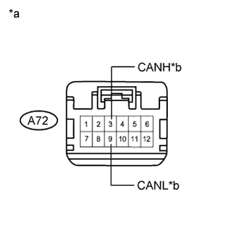 |
Measure the resistance according to the value(s) in the table below.
| Tester Connection | Switch Condition | Specified Condition |
| A72-3 (CANH) - A72-9 (CANL) | Power switch off | 1 MΩ or higher |
| *a | Front view of wire harness connector (to CAN No. 3 Junction Connector) |
| *b | to Skid Control ECU |
|
| ||||
| OK | |
|
| 30.CHECK FOR SHORT IN CAN BUS LINES (SKID CONTROL ECU) |
Reconnect the instrument panel wire and engine room main wire to the CAN No. 3 junction connector.
|
Measure the resistance according to the value(s) in the table below.
| Tester Connection | Switch Condition | Specified Condition |
| A61-35 (CA2H) - A61-34 (CA2L) | Power switch off | 54 to 69 Ω |
| *a | Front view of wire harness connector (to Skid Control ECU) |
| Result | Proceed to |
| OK (for LHD) | A |
| OK (for RHD) | B |
| NG | C |
|
| ||||
|
| ||||
| A | ||
| ||
| ||
| 31.CHECK FOR SHORT IN CAN BUS LINES (ECM) |
Reconnect the instrument panel wire and engine room main wire to the CAN No. 3 junction connector.
|
Disconnect the ECM connector.
Measure the resistance according to the value(s) in the table below.
| Tester Connection | Switch Condition | Specified Condition |
| A60-12 (CANP) - A60-4 (CANN) | Power switch off | 108 to 132 Ω |
| *a | Front view of wire harness connector (to ECM) |
|
| ||||
| OK | ||
| ||
| ||
| 32.CHECK FOR SHORT IN CAN BUS LINE (CAN NO. 5 J/C) |
Disconnect the wire harness connector from the CAN No. 5 junction connector rear side.
Measure the resistance according to the value(s) in the table below.
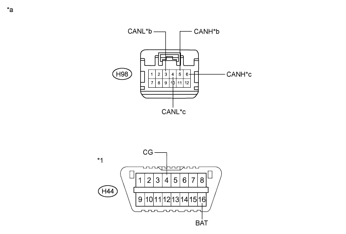
| Tester Connection | Condition | Specified Condition | Purpose | Connected to |
| H98-6 (CANH) - H44-4 (CG) | Power switch off | 200 Ω or higher | Inspection for CANH ground short | Power management control ECU |
| H98-4 (CANL) - H44-4 (CG) | Power switch off | 200 Ω or higher | Inspection for CANL ground short | |
| H98-5 (CANH) - H44-4 (CG) | Power switch off | 200 Ω or higher | Inspection for CANH ground short | Air conditioning amplifier assembly |
| H98-3 (CANL) - H44-4 (CG) | Power switch off | 200 Ω or higher | Inspection for CANL ground short | |
| H98-6 (CANH) - H44-16 (BAT) | Cable disconnected from negative (-) auxiliary battery terminal | 6 kΩ or higher | Inspection for CANH +B short | Power management control ECU |
| H98-4 (CANL) - H44-16 (BAT) | Cable disconnected from negative (-) auxiliary battery terminal | 6 kΩ or higher | Inspection for CANL +B short | |
| H98-5 (CANH) - H44-16 (BAT) | Cable disconnected from negative (-) auxiliary battery terminal | 6 kΩ or higher | Inspection for CANH +B short | Air conditioning amplifier assembly |
| H98-3 (CANL) - H44-16 (BAT) | Cable disconnected from negative (-) auxiliary battery terminal | 6 kΩ or higher | Inspection for CANL +B short |
| *1 | DLC3 | - | - |
| *a | Front view of wire harness connector (to CAN No. 5 Junction Connector) | *b | to Air Conditioning Amplifier Assembly |
| *c | to Power Management Control ECU | - | - |
|
| ||||
| OK | |
|
| 33.CHECK FOR SHORT IN CAN BUS LINE (CAN NO. 5 J/C MAIN LINE) |
Disconnect the wire harness connector from CAN No. 5 junction connector front side.
Measure the resistance according to the value(s) in the table below.
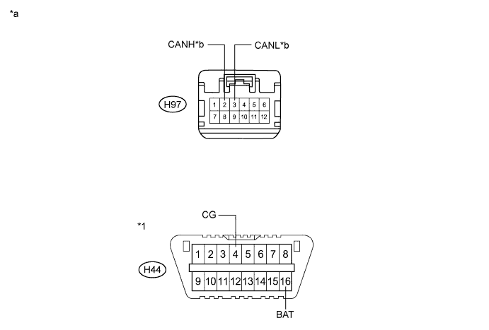
| Tester Connection | Condition | Specified Condition | Purpose | Connected to |
| H97-2 (CANH) - H44-4 (CG) | Power switch off | 200 Ω or higher | Inspection for CANH ground short | CAN No. 1 junction connector |
| H97-3 (CANL) - H44-4 (CG) | Power switch off | 200 Ω or higher | Inspection for CANL ground short | |
| H97-2 (CANH) - H44-16 (BAT) | Cable disconnected from negative (-) auxiliary battery terminal | 6 kΩ or higher | Inspection for CANH +B short | |
| H97-3 (CANL) - H44-16 (BAT) | Cable disconnected from negative (-) auxiliary battery terminal | 6 kΩ or higher | Inspection for CANL +B short |
| *1 | DLC3 | - | - |
| *a | Front view of wire harness connector (to CAN No. 5 Junction Connector) | *b | to CAN No. 1 Junction Connector |
| Result | Proceed to |
| OK | A |
| NG (for LHD) | B |
| NG (for RHD) | C |
|
| ||||
|
| ||||
| A | ||
| ||
| ||
| 34.CHECK FOR SHORT IN CAN BUS LINE (CAN NO. 5 J/C - CAN NO. 1 J/C) |
Disconnect the instrument panel wire from the CAN No. 1 junction connector.
Measure the resistance according to the value(s) in the table below.
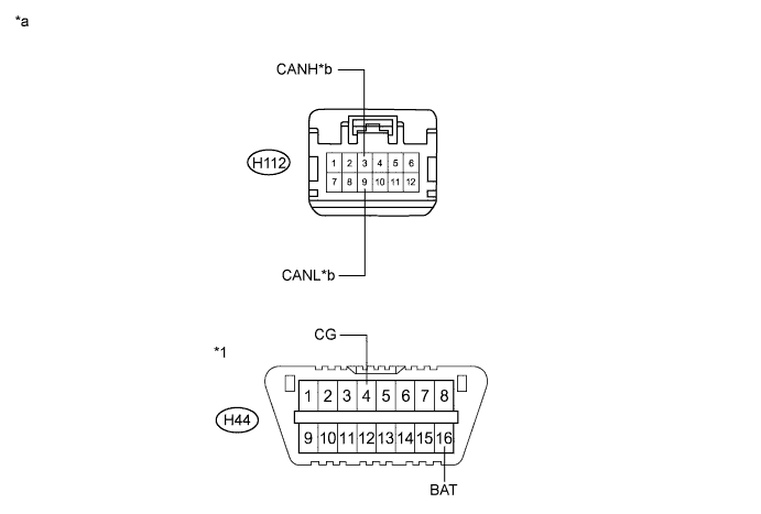
| Tester Connection | Condition | Specified Condition | Purpose | Connected to |
| H112-3 (CANH) - H44-4 (CG) | Power switch off | 200 Ω or higher | Inspection for CANH ground short | CAN No. 5 junction connector |
| H112-9 (CANL) - H44-4 (CG) | Power switch off | 200 Ω or higher | Inspection for CANL ground short | |
| H112-3 (CANH) - H44-16 (BAT) | Cable disconnected from negative (-) auxiliary battery terminal | 6 kΩ or higher | Inspection for CANH +B short | |
| H112-9 (CANL) - H44-16 (BAT) | Cable disconnected from negative (-) auxiliary battery terminal | 6 kΩ or higher | Inspection for CANL +B short |
| *1 | DLC3 | - | - |
| *a | Front view of wire harness connector (to CAN No. 1 Junction Connector) | *b | to CAN No. 5 Junction Connector |
|
| ||||
| OK | |
|
| 35.CHECK FOR SHORT IN CAN BUS LINE (CAN NO. 1 J/C) |
Disconnect the engine room main wire from the CAN No. 1 junction connector.
Measure the resistance according to the value(s) in the table below.
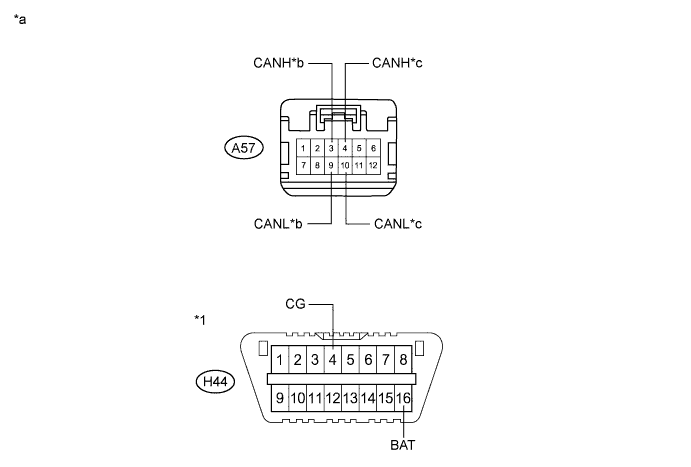
| Tester Connection | Condition | Specified Condition | Purpose | Connected to |
| A57-3 (CANH) - H44-4 (CG) | Power switch off | 200 Ω or higher | Inspection for CANH ground short | Skid control ECU |
| A57-9 (CANL) - H44-4 (CG) | Power switch off | 200 Ω or higher | Inspection for CANL ground short | |
| A57-4 (CANH) - H44-4 (CG) | Power switch off | 200 Ω or higher | Inspection for CANH ground short | ECM |
| A57-10 (CANL) - H44-4 (CG) | Power switch off | 200 Ω or higher | Inspection for CANL ground short | |
| A57-3 (CANH) - H44-16 (BAT) | Cable disconnected from negative (-) auxiliary battery terminal | 6 kΩ or higher | Inspection for CANH +B short | Skid control ECU |
| A57-9 (CANL) - H44-16 (BAT) | Cable disconnected from negative (-) auxiliary battery terminal | 6 kΩ or higher | Inspection for CANL +B short | |
| A57-4 (CANH) - H44-16 (BAT) | Cable disconnected from negative (-) auxiliary battery terminal | 6 kΩ or higher | Inspection for CANH +B short | ECM |
| A57-10 (CANL) - H44-16 (BAT) | Cable disconnected from negative (-) auxiliary battery terminal | 6 kΩ or higher | Inspection for CANL +B short |
| *1 | DLC3 | - | - |
| *a | Front view of wire harness connector (to CAN No. 1 Junction Connector) | *b | to Skid Control ECU |
| *c | to ECM | - | - |
|
| ||||
| OK | ||
| ||
| ||
| 36.CHECK CAN BUS LINE (ECU) |
Disconnect the connector that includes terminals CANH and CANL from the ECU to which the bus line shorted to B+ or shorted to GND is connected.
|
Measure the resistance according to the value(s) in the table below.
| Tester Connection | Condition | Specified Condition | Purpose |
| H4-31 (CA3P) - H4-4 (E12) | Power switch off | 200 Ω or higher | Below 200 Ω: CANH ground short |
| H4-30 (CA3N) - H4-4 (E12) | Power switch off | 200 Ω or higher | Below 200 Ω: CANL ground short |
| H4-31 (CA3P) - H4-7 (AM21) | Cable disconnected from negative (-) auxiliary battery terminal | 6 kΩ or higher | Below 6 kΩ: CANH +B short |
| H4-30 (CA3N) - H4-7 (AM21) | Cable disconnected from negative (-) auxiliary battery terminal | 6 kΩ or higher | Below 6 kΩ: CANL +B short |
| *a | Component with harness connector (Power Management Control ECU) |
|
| ||||
| OK | ||
| ||
| ||
| 37.CHECK FOR SHORT IN CAN BUS LINE (CAN NO. 5 J/C - CAN NO. 3 J/C) |
Disconnect the instrument panel wire from the CAN No. 3 junction connector.
Measure the resistance according to the value(s) in the table below.
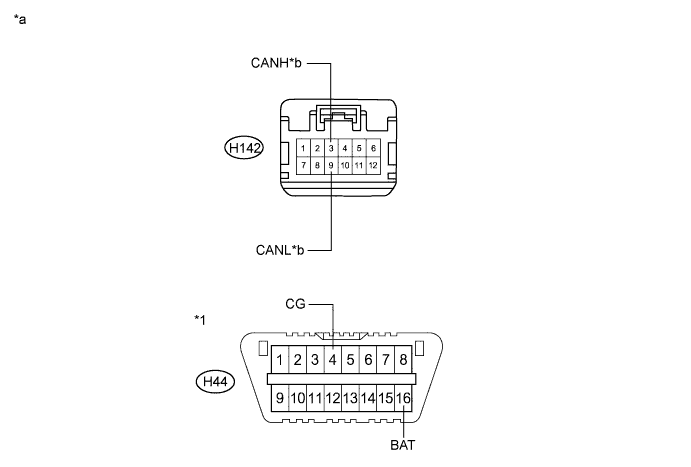
| Tester Connection | Condition | Specified Condition | Purpose | Connected to |
| H142-3 (CANH) - H44-4 (CG) | Power switch off | 200 Ω or higher | Inspection for CANH ground short | CAN No. 5 junction connector |
| H142-9 (CANL) - H44-4 (CG) | Power switch off | 200 Ω or higher | Inspection for CANL ground short | |
| H142-3 (CANH) - H44-16 (BAT) | Cable disconnected from negative (-) auxiliary battery terminal | 6 kΩ or higher | Inspection for CANH +B short | |
| H142-9 (CANL) - H44-16 (BAT) | Cable disconnected from negative (-) auxiliary battery terminal | 6 kΩ or higher | Inspection for CANL +B short |
| *1 | DLC3 | - | - |
| *a | Front view of wire harness connector (to CAN No. 1 Junction Connector) | *b | to CAN No. 5 Junction Connector |
|
| ||||
| OK | |
|
| 38.CHECK FOR SHORT IN CAN BUS LINE (CAN NO. 3 J/C) |
Disconnect the engine room main wire from the CAN No. 3 junction connector.
Measure the resistance according to the value(s) in the table below.
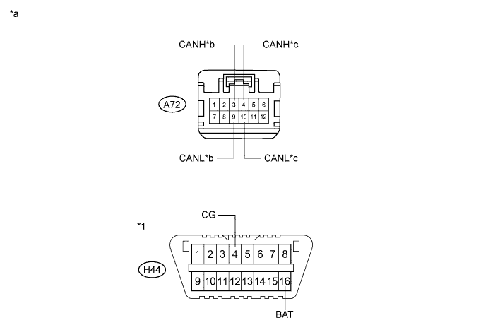
| Tester Connection | Condition | Specified Condition | Purpose | Connected to |
| A72-3 (CANH) - H44-4 (CG) | Power switch off | 200 Ω or higher | Inspection for CANH ground short | Skid control ECU |
| A72-9 (CANL) - H44-4 (CG) | Power switch off | 200 Ω or higher | Inspection for CANL ground short | |
| A72-4 (CANH) - H44-4 (CG) | Power switch off | 200 Ω or higher | Inspection for CANH ground short | ECM |
| A72-10 (CANL) - H44-4 (CG) | Power switch off | 200 Ω or higher | Inspection for CANL ground short | |
| A72-3 (CANH) - H44-16 (BAT) | Cable disconnected from negative (-) auxiliary battery terminal | 6 kΩ or higher | Inspection for CANH +B short | Skid control ECU |
| A72-9 (CANL) - H44-16 (BAT) | Cable disconnected from negative (-) auxiliary battery terminal | 6 kΩ or higher | Inspection for CANL +B short | |
| A72-4 (CANH) - H44-16 (BAT) | Cable disconnected from negative (-) auxiliary battery terminal | 6 kΩ or higher | Inspection for CANH +B short | ECM |
| A72-10 (CANL) - H44-16 (BAT) | Cable disconnected from negative (-) auxiliary battery terminal | 6 kΩ or higher | Inspection for CANL +B short |
| *1 | DLC3 | - | - |
| *a | Front view of wire harness connector (to CAN No. 3 Junction Connector) | *b | to Skid Control ECU |
| *c | to ECM | - | - |
|
| ||||
| OK | ||
| ||
| ||
| 39.CHECK FOR SHORT IN CAN BUS LINE (ECU) |
Disconnect the connector that includes terminals CANH and CANL from the ECU to which the bus line shorted to B+ or shorted to GND is connected.
|
Measure the resistance according to the value(s) in the table below.
| Tester Connection | Condition | Specified Condition | Purpose |
| H4-31 (CA3P) - H4-4 (E12) | Power switch off | 200 Ω or higher | Below 200 Ω: CANH ground short |
| H4-30 (CA3N) - H4-4 (E12) | Power switch off | 200 Ω or higher | Below 200 Ω: CANL ground short |
| H4-31 (CA3P) - H4-7 (AM21) | Cable disconnected from negative (-) auxiliary battery terminal | 6 kΩ or higher | Below 6 kΩ: CANH +B short |
| H4-30 (CA3N) - H4-7 (AM21) | Cable disconnected from negative (-) auxiliary battery terminal | 6 kΩ or higher | Below 6 kΩ: CANL +B short |
| *a | Component with harness connector (Power Management Control ECU) |
|
| ||||
| OK | ||
| ||
| ||


