DTC B2799 Engine Immobiliser System Malfunction |
| DTC Code | DTC Detection Condition | Trouble Area | DTC Output Confirmation Operation |
| B2799 | Either condition is met (1 trip detection logic*):
|
| Either condition is met:
|
| Vehicle Condition when Malfunction Detected | Fail-safe Operation when Malfunction Detected |
| Hybrid control system cannot be started | - |
| DTC Code | Data List and Active Test |
| B2799 | - |
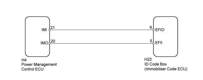
| 1.CLEAR DTC |
Clear the DTCs (Click here).
| NEXT | |
 |
| 2.CHECK FOR DTC |
Check for DTCs (Click here).
|
| ||||
| OK | ||
 | ||
| ||
| 3.CHECK POWER MANAGEMENT CONTROL ECU (IMO) |
Using an oscilloscope, check the waveform.
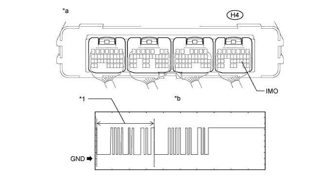
| *1 | Waveform 1 | - | - |
| *a | Component with harness connected (Power Management Control ECU) | *b | Normal Waveform |
| Item | Content |
| Tester Connection | H4-20 (IMO) - Body ground |
| Tool Setting | 2 V/DIV., 200 ms./DIV. |
| Condition | Within 3 seconds of hybrid control system start or within 3 seconds of power switch turned on (IG) after auxiliary battery cable disconnected and reconnected |
| Result | Proceed to |
| Normal waveform | A |
| Waveform 1 has abnormal wavelength or shape | B |
| Terminal IMO stuck high (12 V) | |
| Terminal IMO stuck low (2.4 V or less) | C |
|
| ||||
|
| ||||
| A | |
|
| 4.CHECK POWER MANAGEMENT CONTROL ECU (IMI) |
Using an oscilloscope, check the waveform.
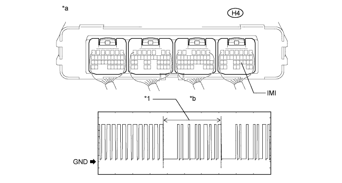
| *1 | Waveform 2 | - | - |
| *a | Component with harness connected (Power Management Control ECU) | *b | Normal Waveform |
| Item | Content |
| Tester Connection | H4-21 (IMI) - Body ground |
| Tool Setting | 2 V/DIV., 200 ms./DIV. |
| Condition | Power switch on (IG) |
| Result | Proceed to |
| Normal waveform | A |
| Waveform 2 not output, or has abnormal wavelength or shape | B |
|
| ||||
| A | |
|
| 5.REGISTER RECOGNITION CODES |
Register the recognition codes in the ECUs.
| NEXT | |
|
| 6.REGISTER ECU COMMUNICATION ID |
Register the ECU communication ID.
Check that the hybrid control system can be started with a registered key.
|
| ||||
| OK | ||
| ||
| ||
| 7.REPLACE POWER MANAGEMENT CONTROL ECU |
Temporarily replace the power management control ECU with a new or known good one (Click here).
| NEXT | |
|
| 8.CLEAR DTC |
Clear the DTCs (Click here).
| NEXT | |
|
| 9.CHECK FOR DTC |
Check for DTCs (Click here).
|
| ||||
| OK | ||
| ||
| ||
| 10.CHECK ID CODE BOX (IMMOBILISER CODE ECU) (IMO) |
Disconnect the H4 ECU connector.
Measure the voltage according to the value(s) in the table below.
| Tester Connection | Condition | Specified Condition |
| H4-20 (IMO) - Body ground | Power switch on (IG) | 11 to 14 V |
|
| ||||
| A | |
|
| 11.CHECK HARNESS AND CONNECTOR (ID CODE BOX - POWER MANAGEMENT CONTROL ECU) |
Disconnect the H22 box connector.
Disconnect the H4 ECU connector.
Measure the resistance according to the value(s) in the table below.
| Tester Connection | Condition | Specified Condition |
| H22-5 (EFII) - H4-20 (IMO) | Always | Below 1 Ω |
| H4-20 (IMO) - Body ground | Always | 10 kΩ or higher |
|
| ||||
| OK | |
|
| 12.REPLACE ID CODE BOX (IMMOBILISER CODE ECU) |
Replace the ID code box (immobiliser code ECU) with a new one.
| NEXT | |
|
| 13.CLEAR DTC |
Clear the DTCs (Click here).
Register the recognition codes in the ECUs.
Register the ECU communication ID.
| NEXT | |
|
| 14.CHECK FOR DTC |
Check for DTCs (Click here).
|
| ||||
| OK | ||
| ||
| ||
| 15.REPLACE POWER MANAGEMENT CONTROL ECU |
Temporarily replace the power management control ECU with a new or known good one (Click here).
| NEXT | |
|
| 16.CLEAR DTC |
Clear the DTCs (Click here).
| NEXT | |
|
| 17.CHECK FOR DTC |
Check for DTCs (Click here).
|
| ||||
| OK | ||
| ||
| ||


