MILLIMETER WAVE RADAR SENSOR > ADJUSTMENT

for Preparation Click here


1. ADJUST MILLIMETER WAVE RADAR SENSOR ASSEMBLY


E219881E01
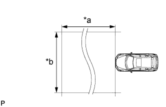
Text in Illustration 
*a
Approx. 10 m
*b
Approx. 14 m

CAUTION:
Radio frequency radiation exposure information:
  1. This equipment should be kept with minimum distance of 20 cm (7.87 in.) between the radiator (antenna) and your body at all times during adjustment.
  2. This transmitter must not be co-located or operating in conjunction with any other antenna or transmitter.

NOTICE:
  1. Perform measurements on a level surface.
  2. Make sure that no large pieces of metal are within a 10 m (32.8 ft.) x 14 m (45.9 ft.) area in front of the vehicle. If possible, the surrounding area should also be free of large metal objects.

  1. Before adjusting the radar beam axis, prepare the vehicle as follows.

    1. Check the tire pressure and adjust it if necessary.

    2. Remove all excess weight from the vehicle (luggage, heavy objects, etc.).

    3. Remove the radiator support opening cover (Click here).


    E214952E01
  1. Check and adjust the vertical direction of the radar sensor.
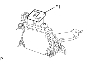
    Text in Illustration 
    *1
    Level

    1. Remove dust, oil and foreign matter from the radar sensor's level rack.

    2. Set a level on the radar sensor's level rack.


    3. E219867E01
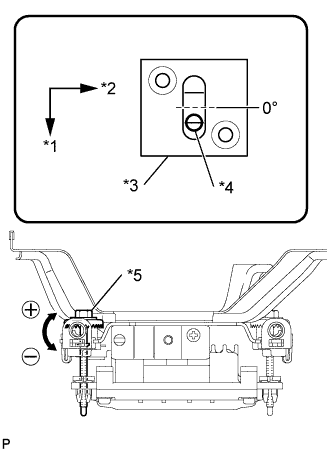
    4. Check that the level's air bubble is within the red frame.
      Text in Illustration 
      *1
      Vehicle Front
      *2
      LH
      *3
      Level
      *4
      Air Bubble
      *5
      Bolt A

      OK:
      Level's air bubble is within red frame.

      If the bubble is not within the red frame, use a screwdriver to adjust bolt A until the air bubble is within the red frame.

      HINT:
      1. The adjustable range within the level's red frame is +/- 0.2°.
      2. The target angle is +0.2° (upward angle of 0.2°).

        Adjustment:
        Adjustment Direction
        Adjustment Procedure
        Adjustment Angle
        Vertical adjustment
        Upward direction: Turn screwdriver to negative (-) side
        When screwdriver is turned once, adjustment changes by about 0.12°.
        Downward direction: Turn screwdriver to positive (+) side


    E219868E01
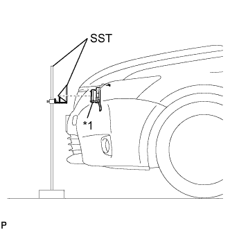
  1. Adjust the reflector height.
    Text in Illustration 
    *1
    Millimeter Wave Radar Sensor

    1. Adjust the reflector so that the center of SST reflector is the same height as the millimeter wave radar sensor or the center of emblem.
      SST
      09870-60000   (09870-60010)
      09870-60040  

      HINT:
      Prepare a 10 m (32.8 ft.) string, a string with a sharp-pointed weight (plumb bob), and a 5 m (16.4 ft.) tape measure.


    E219872E01
  1. Place the reflector.

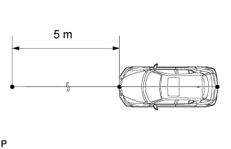
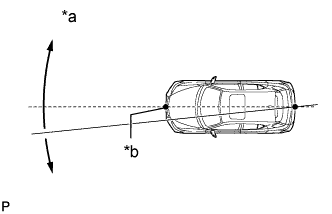
    1. Hang the string (with weight) from the center of the vehicle's rear emblem. Mark the vehicle's rear center point on the ground. Repeat for the front of the vehicle.


    2. E219883E01
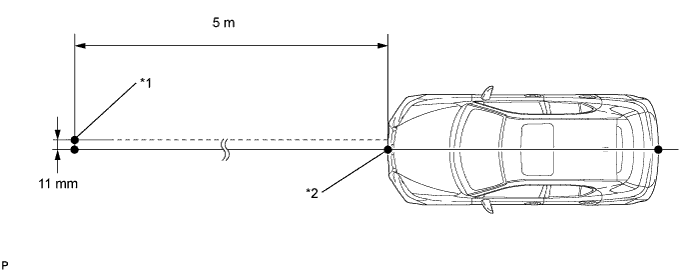
    3. Set one end of the 10 m (32.8 ft.) string on the vehicle's rear center point. Run the string over the vehicle's front center point to a position 5 m (16.4 ft.) beyond the vehicle's front center point, as shown in the illustration. Mark the 5 m (16.4 ft.) position.
      Text in Illustration 
      *a
      Adjust center by moving string to right and left
      *b
      Extend string through front center mark


    4. Using a tape measure, measure 11 mm (0.433 in.) to the right of the 5 m (16.4 ft.) position. Place the reflector at that position.
      NOTICE:
      Perform the operation as precisely as possible.


      E219870E01


      Text in Illustration 
      *1
      Reflector Placement Point
      *2
      Millimeter Wave Radar Sensor Position

  1. Check the radar beam axis.

    HINT:
    If a screen indicating an error is displayed while performing this procedure, perform the procedure again from *1.


    1. Connect the intelligent tester to the DLC3.

    2. Turn the power switch on (IG).

    3. Turn the intelligent tester on, and turn the cruise control main switch on.

    4. Select "Auto" from the intelligent tester display screen.*1

    5. Select "Radar Cruise" from the display screen.

    6. Select "Utility" from the display screen.

    7. Select "Beam Axis Adjustment" from the display screen.

    8. Follow the tester display, and select "Next".

      CAUTION:
      Do not come within 20 cm (7.87 in.) of the radar sensor.

      NOTICE:
      1. Turn the cruise control main switch on before pressing Next.
      2. Make sure that there is at least 20 cm (7.87 in.) between the radar sensor and any nearby individuals.

    9. Check the following items on the radar cruise divergence data screen.

      NOTICE:
      While using the intelligent tester's beam axis adjustment mode, the actual direction and angle of the radar sensor may be different from the intelligent tester's data. In such a case, the deviation is displayed on the combination meter's multi-information display.

      1. Confirm that the distance value is approximately 5 m (16.4 ft.).

        HINT:
        1. A value between 0.0 m (0.0 ft.) and 6.3 m (20.7 ft.) is indicated.
        2. If the distance is 0.0 m (0.0 ft.), the sensor cannot detect the target. Reconfirm that there is no metal in the specified area in front of the vehicle (refer to the notice at the beginning of this adjustment procedure).

      2. Confirm that the left/right side value is between 0.0 m (0.0 ft.) and 6.3 m (20.7 ft.).

        HINT:
        If the distance is 0.0 m (0.0 ft.), the sensor cannot detect the target. Reconfirm that there is no metal in the specified area in front of the vehicle (refer to the notice at the beginning of this adjustment procedure).


  1. Check and adjust the horizontal direction of the radar sensor.

    1. Check that the divergence of the radar beam axis is 0°.
      Standard:
      0° (Both right and left)

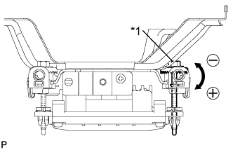
      If the axis is not as specified, use a screwdriver to adjust bolt B until the divergence of the radar beam axis is 0°.


    2. E219871E01
    3. Based on the measured divergence of the beam axis, turn and adjust bolt B for horizontal adjustment of the millimeter wave radar sensor using a screwdriver.
      Text in Illustration 
      *1
      Bolt B

      Adjustment:
      Adjustment Direction
      Adjustment Procedure
      Adjustment Angle
      Horizontal adjustment
      Right direction: Turn screwdriver to positive (+) side.
      When screwdriver is turned once, adjustment changes by about 0.07°.
      Left direction: Turn screwdriver to negative (-) side.

      HINT:
      If the value does not change to 0°, it is possible that the sensor is aiming at something different. Reconfirm that there are no reflective materials in the surrounding area.

    4. Select "Next". The driving learning value is automatically reset.

      HINT:
      A buzzer will sound for 10 seconds or more.

    5. Disconnect the intelligent tester from the DLC3.


  1. Recheck and readjust the vertical direction of the radar sensor.


      E214952E01
    1. Set a level on the radar sensor's level rack.
      Text in Illustration 
      *1
      Level


    2. E219867E01
    3. Check that the level's air bubble is within the red frame.
      Text in Illustration 
      *1
      Vehicle Front
      *2
      LH
      *3
      Level
      *4
      Air Bubble
      *5
      Bolt A

      OK:
      Level's air bubble is within the red frame.

      If the bubble is not within the red frame, use a screwdriver to adjust bolt A until the level's air bubble is within the red frame.

      HINT:
      1. The adjustable range within the red frame is +/- 0.2°.
      2. The target angle is +0.2° (upward angle of 0.2°).

        Adjustment:
        Adjustment Direction
        Adjustment Procedure
        Adjustment Angle
        Vertical adjustment
        Upward direction: Turn screwdriver to negative (-) side
        When screwdriver is turned once, adjustment changes by about 0.12°.
        Downward direction: Turn screwdriver to positive (+) side

  1. After adjusting the radar beam axis, return the vehicle to its original condition.

    1. If any heavy items were removed from the vehicle, return them (luggage, heavy objects, etc.).

    2. Install the radiator support opening cover (Click here).