DTC    U0129    Lost Communication with Brake System Control Module

for Preparation Click here


DESCRIPTION


DTC No.
DTC Detection Condition
Trouble Area
U0129
No communication from the skid control ECU continues.
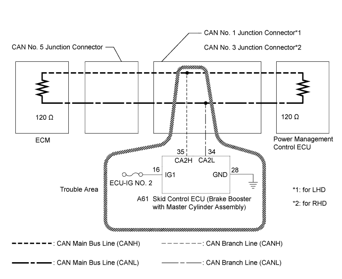
  1. Skid control ECU branch line or connector
  2. Power source circuit of skid control ECU
  3. Skid control ECU (Brake booster with master cylinder assembly)

HINT:
This diagnosis procedure is for when DTC U0129 is output by the power management control ECU (Intelligent tester display: PM2 Gateway).


WIRING DIAGRAM


C234514E03


INSPECTION PROCEDURE

NOTICE:
  1. Turn the power switch off before measuring the resistances between CAN main bus lines and between CAN branch lines.
  2. Turn the power switch off before inspecting CAN bus lines for a ground short.
  3. After the power switch is turned off, check that the key reminder warning system and light reminder warning system are not operating.
  4. Before measuring the resistance, leave the vehicle as is for at least 1 minute and do not operate the power switch, any other switches or the doors. If any doors need to be opened in order to check connectors, open the doors and leave them open.

HINT:
  1. Operating the power switch, any other switches or a door triggers related ECU and sensor communication on the CAN. This communication will cause the resistance value to change.
  2. Even after DTCs are cleared, if a DTC is stored again after driving the vehicle for a while, the malfunction may be occurring due to vibration of the vehicle. In such a case, wiggling the ECUs or wire harness while performing the inspection below may help determine the cause of the malfunction.

1.RECONFIRM DTC OUTPUT
  1. Reconfirm DTCs.

    HINT:
    If DTC U1002 is output from PM2 Gateway of the power management control ECU, this indicates a power management bus malfunction. Troubleshoot for DTC U1002 and check for malfunctions in the power management bus.

    Result:
    Result
    Proceed to
    U1002 is not output from power management control ECU (Intelligent tester display/PM2 Gateway)
    A
    U1002 is output from power management control ECU (Intelligent tester display/PM2 Gateway)
    B


B
GO TO DIAGNOSIS PROCEDURE INDICATED BY OUTPUT DTC (Click here)
A


2.CHECK DTC (BRAKE SYSTEM)
  1. Connect the intelligent tester to the DLC3.

  1. Turn the power switch on (IG).

  1. Turn the intelligent tester on.

  1. Enter the following menus: Chassis / ABS/VSC/TRC / DTC.

    OK:
    DTC C1241 is not output.


NG
GO TO DIAGNOSIS PROCEDURE INDICATED BY OUTPUT DTC (Click here)
OK


3.CHECK CAN BUS LINE FOR DISCONNECTION (SKID CONTROL ECU BRANCH LINE)
  1. Turn the power switch off.


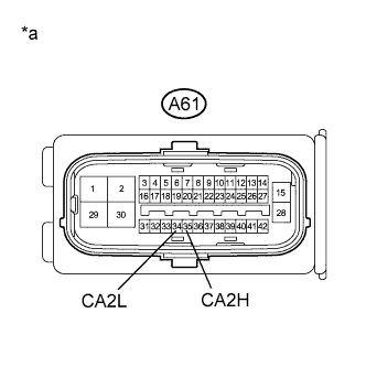
    C209401E68
  1. Disconnect the skid control ECU connector.

  1. Measure the resistance according to the value(s) in the table below.

    Standard Resistance:
    Tester Connection
    Switch Condition
    Specified Condition
    A61-35 (CA2H) - A61-34 (CA2L)
    Power switch off
    54 to 69 Ω

    Text in Illustration 
    *a
    Front view of wire harness connector
    (to Skid Control ECU)

    Result:
    Result
    Proceed to
    OK (for LHD)
    A
    OK (for RHD)
    B
    NG
    C


B
REPLACE BRAKE BOOSTER WITH MASTER CYLINDER ASSEMBLY (SKID CONTROL ECU) (Click here)

C
REPAIR OR REPLACE CAN BRANCH LINE OR CONNECTOR (SKID CONTROL ECU)
A

REPLACE BRAKE BOOSTER WITH MASTER CYLINDER ASSEMBLY (SKID CONTROL ECU) (Click here)