AUDIO AND VISUAL SYSTEM (w/o Navigation System) > Microphone Circuit between Microphone and Radio Receiver |
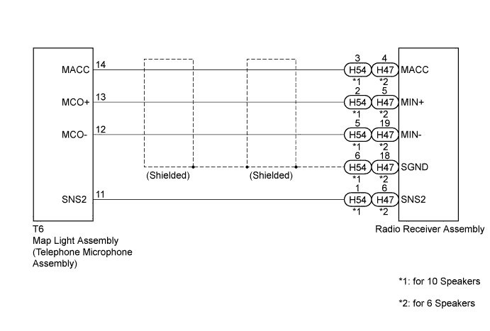
| 1.CHECK HARNESS AND CONNECTOR |
Disconnect the radio receiver assembly and map light assembly connectors.
Measure the resistance according to the value(s) in the table below.
| Tester Connection | Condition | Specified Condition |
| H54-1 (SNS2) - T6-11 (SNS2) | Always | Below 1 Ω |
| H54-3 (MACC) - T6-14 (MACC) | Always | Below 1 Ω |
| H54-2 (MIN+) - T6-13 (MCO+) | Always | Below 1 Ω |
| H54-5 (MIN-) - T6-12 (MCO-) | Always | Below 1 Ω |
| H54-1 (SNS2) - Body ground | Always | 10 kΩ or higher |
| H54-3 (MACC) - Body ground | Always | 10 kΩ or higher |
| H54-2 (MIN+) - Body ground | Always | 10 kΩ or higher |
| H54-5 (MIN-) - Body ground | Always | 10 kΩ or higher |
| H54-6 (SGND) - Body ground | Always | 10 kΩ or higher |
| Tester Connection | Condition | Specified Condition |
| H47-6 (SNS2) - T6-11 (SNS2) | Always | Below 1 Ω |
| H47-4 (MACC) - T6-14 (MACC) | Always | Below 1 Ω |
| H47-5 (MIN+) - T6-13 (MCO+) | Always | Below 1 Ω |
| H47-19 (MIN-) - T6-12 (MCO-) | Always | Below 1 Ω |
| H47-6 (SNS2) - Body ground | Always | 10 kΩ or higher |
| H47-4 (MACC) - Body ground | Always | 10 kΩ or higher |
| H47-5 (MIN+) - Body ground | Always | 10 kΩ or higher |
| H47-19 (MIN-) - Body ground | Always | 10 kΩ or higher |
| H47-18 (SGND) - Body ground | Always | 10 kΩ or higher |
|
| ||||
| OK | |
 |
| 2.INSPECT RADIO RECEIVER ASSEMBLY |
Disconnect the radio receiver assembly connector.
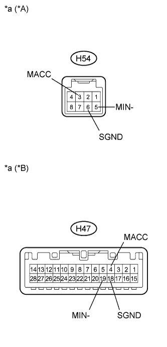 |
Measure the voltage according to the value(s) in the table below.
| Tester Connection | Condition | Specified Condition |
| H54-3 (MACC) - Body ground | Power switch on (ACC) | 4 to 6 V |
| Tester Connection | Condition | Specified Condition |
| H47-4 (MACC) - Body ground | Power switch on (ACC) | 4 to 6 V |
Measure the resistance according to the value(s) in the table below.
| Tester Connection | Condition | Specified Condition |
| H54-6 (SGND) - Body ground | Always | Below 1 Ω |
| H54-5 (MIN-) - Body ground | Always | Below 1 Ω |
| Tester Connection | Condition | Specified Condition |
| H47-18 (SGND) - Body ground | Always | Below 1 Ω |
| H47-19 (MIN-) - Body ground | Always | Below 1 Ω |
| *A | for 10 Speakers |
| *B | for 6 Speakers |
| *a | Component without harness connected (Radio Receiver Assembly) |
|
| ||||
| OK | |
|
| 3.INSPECT MAP LIGHT ASSEMBLY |
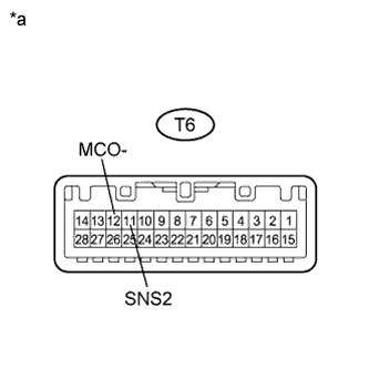 |
Measure the resistance according to the value(s) in the table below.
| Tester Connection | Condition | Specified Condition |
| T6-12 (MCO-) - T6-11 (SNS2) | Always | Below 1 Ω |
| *a | Component without harness connected (Map Light Assembly) |
|
| ||||
| OK | |
|
| 4.INSPECT MAP LIGHT ASSEMBLY |
Reconnect the radio receiver assembly connector.
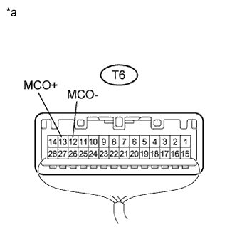 |
Reconnect the map light assembly connector.
Turn the power switch on (ACC).
Connect an oscilloscope to terminals 13 (MCO+) and 12 (MCO-) of the map light assembly connector.
Check the waveform of the telephone microphone assembly using the oscilloscope.
| Result | Proceed to |
| A waveform synchronized with the voice input to the map light assembly is output | A |
| A waveform synchronized with the voice input to the map light assembly is not output | B |
| *a | Component with harness connected (Map Light Assembly) |
|
| ||||
| A | ||
 | ||
| ||
| 5.REPLACE TELEPHONE MICROPHONE ASSEMBLY |
Replace the telephone microphone assembly (Click here).
Check if the same malfunction recurs.
| Result | Proceed to |
| Malfunction does not recur (returns to normal) | A |
| Malfunction recurs | B |
|
| ||||
| A | ||
| ||
| ||


