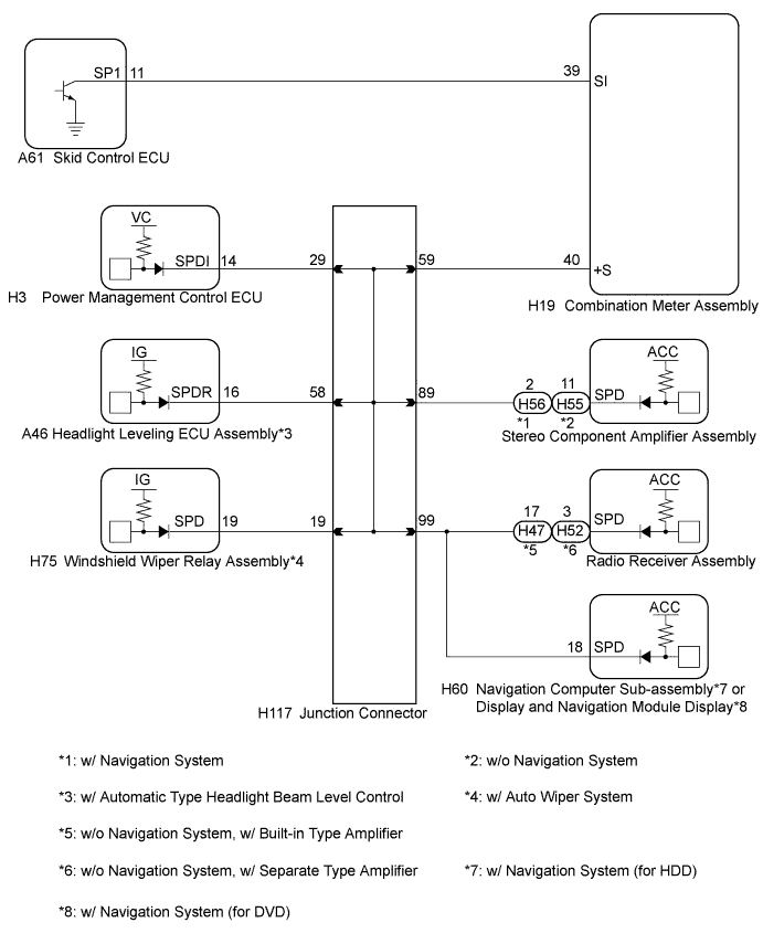
AUDIO AND VISUAL SYSTEM (w/ Navigation System) > Vehicle Speed Signal Circuit between Stereo Component Amplifier and Combination Meter |
| 1.INSPECT COMBINATION METER ASSEMBLY (OUTPUT WAVEFORM) |
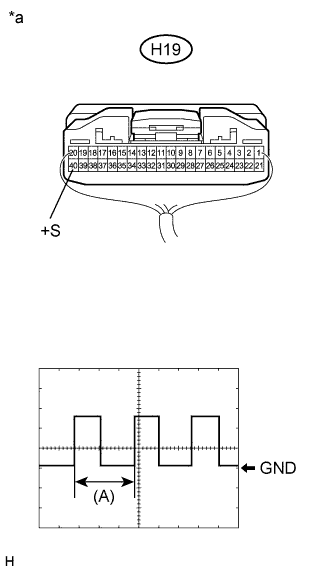 |
Check the output waveform.
Remove the combination meter assembly with the connector still connected.
Connect an oscilloscope to terminal H19-40 (+S) and body ground.
Turn the power switch on (IG).
Turn a wheel slowly.
Check the signal waveform according to the condition(s) in the table below.
| Item | Condition |
| Measurement terminal | H19-40 (+S) - Body ground |
| Tool setting | 5 V/DIV., 20 ms./DIV. |
| Vehicle condition | Wheel being rotated |
| *a | Component with harness connected (Combination Meter Assembly) |
|
| ||||
| OK | |
 |
| 2.CHECK HARNESS AND CONNECTOR |
Disconnect the stereo component amplifier assembly and combination meter assembly connectors.
Measure the resistance according to the value(s) in the table below.
| Tester Connection | Condition | Specified Condition |
| H56-2 (SPD) - H19-40 (+S) | Always | Below 1 Ω |
|
| ||||
| OK | ||
 | ||
| ||
| 3.CHECK HARNESS AND CONNECTOR (STEREO COMPONENT AMPLIFIER ASSEMBLY - JUNCTION CONNECTOR) |
Disconnect the stereo component amplifier assembly connector and junction connector.
Measure the resistance according to the value(s) in the table below.
| Tester Connection | Condition | Specified Condition |
| H56-2 (SPD) - H117-89 | Always | Below 1 Ω |
|
| ||||
| OK | ||
| ||
| ||


