AUDIO AND VISUAL SYSTEM (w/o Navigation System) > Vehicle Speed Signal Circuit between Radio Receiver and Combination Meter

for Preparation Click here


DESCRIPTION

for Automatic Sound Levelizer (ASL):
  1. This circuit is necessary for the Automatic Sound Levelizer (ASL) built into the radio receiver assembly.
    The Automatic Sound Levelizer (ASL) function automatically adjusts the audio system volume level in order to compensate for increased vehicle noise (vehicle noise tends to increase as vehicle speed increases). The ASL adjusts the volume level based upon vehicle speed signals that it receives from the combination meter assembly.
for "Bluetooth":
  1. Speed signals are received from the combination meter assembly and used to cancel "Bluetooth" function operation.
    The radio receiver assembly recognizes that the vehicle is being driven and makes it impossible to connect or register a "Bluetooth" device while driving.

HINT:
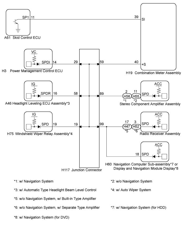
  1. A voltage of 12 V or 5 V is output from each ECU and then input to the combination meter assembly. The signal is changed to a pulse signal at the transistor in the combination meter assembly. Each ECU controls the respective system based on the pulse signal.
  2. If a short occurs in any of the ECUs or in the wire harness connected to an ECU, all systems in the following diagram will not operate normally.


WIRING DIAGRAM


E217460E01


INSPECTION PROCEDURE

1.INSPECT COMBINATION METER ASSEMBLY (OUTPUT WAVEFORM)


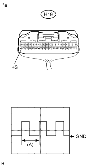
    E210226E04
  1. Check the output waveform.

    1. Remove the combination meter assembly with the connector still connected.

    2. Connect an oscilloscope to terminal H19-40 (+S) and body ground.

    3. Turn the power switch on (IG).

    4. Turn a wheel slowly.

    5. Check the signal waveform according to the condition(s) in the table below.
      Item
      Condition
      Measurement terminal
      H19-40 (+S) - Body ground
      Tool setting
      5 V/DIV., 20 ms./DIV.
      Vehicle condition
      Wheel being rotated

      OK:
      The waveform is similar to that shown in the illustration.

      HINT:
      When the system is functioning normally, one wheel revolution generates 4 pulses. As the vehicle speed increases, the width indicated by (A) in the illustration narrows.

      Text in Illustration 
      *a
      Component with harness connected
      (Combination Meter Assembly)


NG
GO TO METER / GAUGE SYSTEM (Click here)
OK


2.CHECK HARNESS AND CONNECTOR (RADIO RECEIVER ASSEMBLY - COMBINATION METER ASSEMBLY)
  1. Disconnect the radio receiver assembly and combination meter assembly connectors.

  1. Measure the resistance according to the value(s) in the table below.

    Standard Resistance:
    w/ Separate Type Amplifier (for 10 Speakers) 
    Tester Connection
    Condition
    Specified Condition
    H52-3 (SPD) - H19-40 (+S)
    Always
    Below 1 Ω
    w/ Built-in Type Amplifier (for 6 Speakers) 
    Tester Connection
    Condition
    Specified Condition
    H47-17 (SPD) - H19-40 (+S)
    Always
    Below 1 Ω


NG
Go to step 3
OK

REPLACE RADIO RECEIVER ASSEMBLY (Click here)  

3.CHECK HARNESS AND CONNECTOR (RADIO RECEIVER ASSEMBLY - JUNCTION CONNECTOR)
  1. Disconnect the radio receiver assembly connector and junction connector.

  1. Measure the resistance according to the value(s) in the table below.

    Standard Resistance:
    w/ Separate Type Amplifier (for 10 Speakers) 
    Tester Connection
    Condition
    Specified Condition
    H52-3 (SPD) - H117-99
    Always
    Below 1 Ω
    w/ Built-in Type Amplifier (for 6 Speakers) 
    Tester Connection
    Condition
    Specified Condition
    H47-17 (SPD) - H117-99
    Always
    Below 1 Ω


NG
REPAIR OR REPLACE HARNESS OR CONNECTOR
OK

GO TO METER / GAUGE SYSTEM (Click here)