LIGHTING SYSTEM > Speed Signal Circuit |
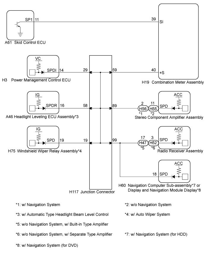
| 1.CHECK COMBINATION METER SYSTEM |
The circuits that send vehicle speed signals to this system are inspected in the meter section (Click here).
During inspection for the meter system, if there is an instruction that indicates to go back to inspections for the lighting system, proceed to the next step.
| NEXT | |
 |
| 2.CHECK HARNESS AND CONNECTOR (HEADLIGHT LEVELING ECU ASSEMBLY - COMBINATION METER ASSEMBLY) |
Disconnect the H19 combination meter assembly connector.
Disconnect the A46 headlight leveling ECU assembly connector.
Measure the resistance according to the value(s) in the table below.
| Tester Connection | Condition | Specified Condition |
| A46-16 (SPDR) - H19-40 (+S) | Always | Below 1 Ω |
|
| ||||
| OK | |
|
| 3.INSPECT COMBINATION METER ASSEMBLY (OUTPUT WAVEFORM) |
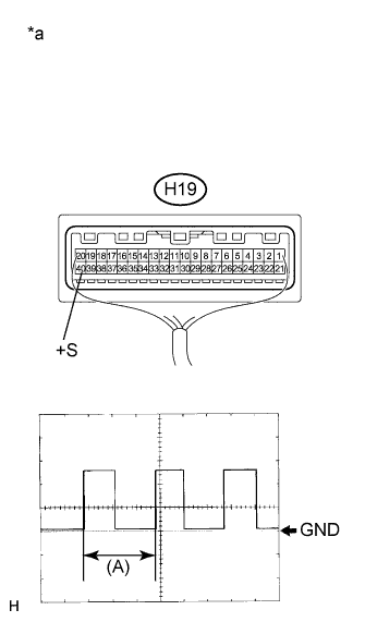 |
Check the output waveform.
Remove the combination meter assembly with the connector still connected.
Connect an oscilloscope to terminal H19-40 (+S) and body ground.
Turn the power switch on (IG).
Check the signal waveform according to the condition(s) in the table below.
| Item | Condition |
| Tool setting | 5 V/DIV., 20 ms./DIV. |
| Vehicle condition | Driving at approx. 20 km/h (12 mph) |
| *a | Component with harness connected (Combination Meter Assembly) |
|
| ||||
| OK | ||
 | ||
| ||

