POWER MIRROR CONTROL SYSTEM (w/ Memory) > Power Mirror Surface Position is not Memorized |
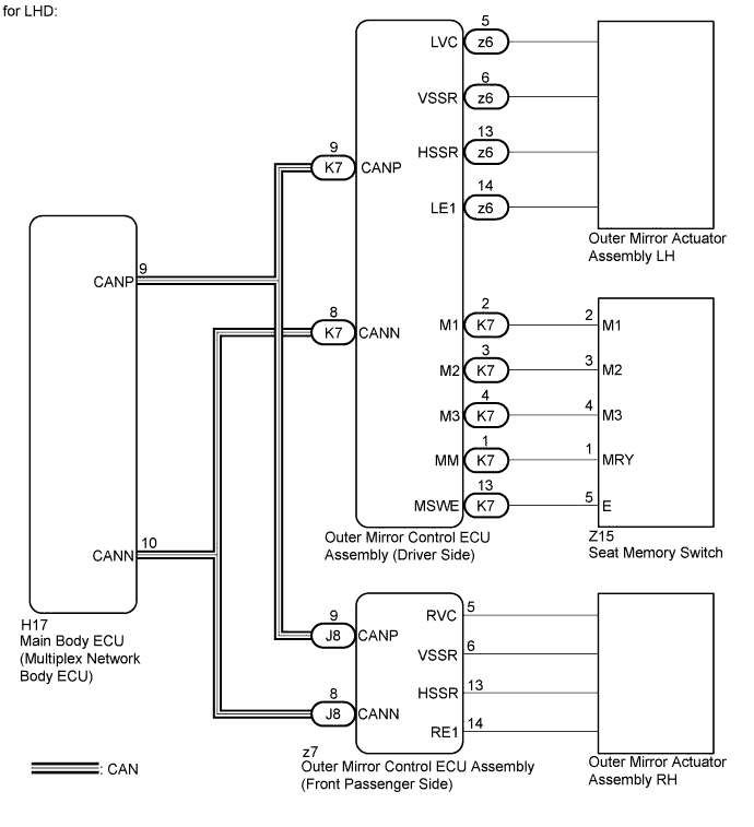
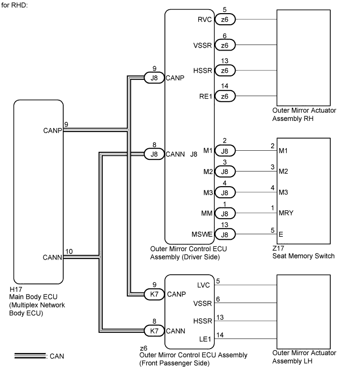
| 1.CHECK CAN COMMUNICATION SYSTEM |
Use the intelligent tester to check if the CAN communication system is functioning normally (Click here).
|
| ||||
| OK | |
 |
| 2.READ VALUE USING INTELLIGENT TESTER (SEAT MEMORY SWITCH) |
Connect the intelligent tester to the DLC3.
Turn the power switch on (IG).
Turn the intelligent tester on.
Enter the following menus: Body / Mirror L*1 or Mirror R*2/ Data List.
Read the Data List according to the display on the intelligent tester.
| Tester Display | Measurement Item/Range | Normal Condition | Diagnostic Note |
| Seat Memory Switch1 | Seat memory switch M1 signal/ ON or OFF | ON: Seat memory switch M1 on OFF: Seat memory switch M1 off | - |
| Seat Memory Switch2 | Seat memory switch M2 signal/ ON or OFF | ON: Seat memory switch M2 on OFF: Seat memory switch M2 off | - |
| Seat Memory Switch3 | Seat memory switch M3 signal/ ON or OFF | ON: Seat memory switch M3 on OFF: Seat memory switch M3 off | - |
| Seat Memory Set SW | Seat memory switch SET signal/ ON or OFF | ON: Seat memory switch SET on OFF: Seat memory switch SET off | - |
|
| ||||
| OK | |
|
| 3.CHECK SEAT MEMORY SWITCH FUNCTION |
When any seat memory switch (M1, M2 or M3 switch) is pressed, check that the driver side seat moves to the memorized position.
|
| ||||
| OK | |
|
| 4.CHECK MEMORY AND REACTIVATION FUNCTION |
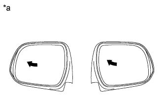 |
Turn the power switch on (IG).
Using the outer mirror switch assembly, turn the mirror surface to the fully left position.
Press the M1 switch while the SET switch is being pressed.
Check that the buzzer sounds for 0.5 seconds and the mirror surface position is memorized.
Using the outer mirror switch assembly, turn the mirror surface to the fully right position.
Press the M1 switch.
Check that the buzzer sounds for 0.1 seconds and the outer mirror automatically moves to the recorded fully left position.
| Result | Proceed to |
| Memory and reactivation functions on both mirrors are not normal | A |
| Memory and reactivation function on RH side mirrors is not normal | B |
| Memory and reactivation function on LH side mirror is not normal | C |
| *a | Turn to Left Fully |
|
| ||||
|
| ||||
| A | ||
 | ||
| ||
| 5.CHECK HARNESS AND CONNECTOR (SEAT MEMORY SWITCH - OUTER MIRROR CONTROL ECU ASSEMBLY) |
for LHD:
Disconnect the K7 connector from the outer mirror control ECU assembly.
Disconnect the z15 connector from the seat memory switch.
Measure the resistance according to the value(s) in the table below.
| Tester Connection | Condition | Specified Condition |
| z15-1 (MRY) - K7-1 (MM) | Always | Below 1 Ω |
| z15-2 (M1) - K7-2 (M1) | Always | Below 1 Ω |
| z15-3 (M2) - K7-3 (M2) | Always | Below 1 Ω |
| z15-4 (M3) - K7-4 (M3) | Always | Below 1 Ω |
| z15-5 (E) - K7-13 (MSWE) | Always | Below 1 Ω |
| z15-1 (MRY) - Body ground | Always | 10 kΩ or higher |
| z15-2 (M1) - Body ground | Always | 10 kΩ or higher |
| z15-3 (M2) - Body ground | Always | 10 kΩ or higher |
| z15-4 (M3) - Body ground | Always | 10 kΩ or higher |
| z15-1 (MRY) - Body ground | Always | 10 kΩ or higher |
for RHD:
Disconnect the J8 connector from the outer mirror control ECU assembly.
Disconnect the z17 connector from the seat memory switch.
Measure the resistance according to the value(s) in the table below.
| Tester Connection | Condition | Specified Condition |
| z17-1 (MRY) - J8-1 (MM) | Always | Below 1 Ω |
| z17-2 (M1) - J8-2 (M1) | Always | Below 1 Ω |
| z17-3 (M2) - J8-3 (M2) | Always | Below 1 Ω |
| z17-4 (M3) - J8-4 (M3) | Always | Below 1 Ω |
| z17-5 (E) - J8-13 (MSWE) | Always | Below 1 Ω |
| z17-1 (MRY) - Body ground | Always | 10 kΩ or higher |
| z17-2 (M1) - Body ground | Always | 10 kΩ or higher |
| z17-3 (M2) - Body ground | Always | 10 kΩ or higher |
| z17-4 (M3) - Body ground | Always | 10 kΩ or higher |
| z17-1 (MRY) - Body ground | Always | 10 kΩ or higher |
|
| ||||
| OK | |
|
| 6.INSPECT SEAT MEMORY SWITCH |
for LHD:
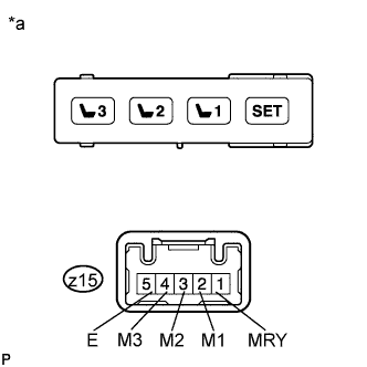 |
Remove the seat memory switch (Click here).
Measure the resistance according to the value(s) in the table below.
| Tester Connection | Condition | Specified Condition |
| z15-2 (M1) - z15-5 (E) | M1 Switch off → on | 10 kΩ or higher → Below 1 Ω |
| z15-3 (M2) - z15-5 (E) | M2 Switch off → on | 10 kΩ or higher → Below 1 Ω |
| z15-4 (M3) - z15-5 (E) | M3 Switch off → on | 10 kΩ or higher → Below 1 Ω |
| z15-1 (MRY) - z15-5 (E) | SET Switch off → on | 10 kΩ or higher → Below 1 Ω |
| *a | Component without harness connected (Seat Memory Switch) |
for RHD:
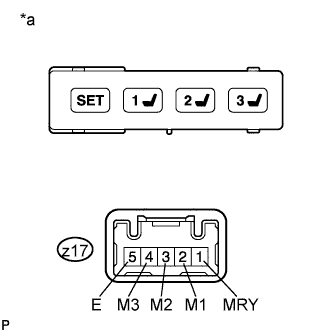 |
Remove the seat memory switch (Click here).
Measure the resistance according to the value(s) in the table below.
| Tester Connection | Condition | Specified Condition |
| z17-2 (M1) - z17-5 (E) | M1 Switch off → on | 10 kΩ or higher → Below 1 Ω |
| z17-3 (M2) - z17-5 (E) | M2 Switch off → on | 10 kΩ or higher → Below 1 Ω |
| z17-4 (M3) - z17-5 (E) | M3 Switch off → on | 10 kΩ or higher → Below 1 Ω |
| z17-1 (MRY) - z17-5 (E) | SET Switch off → on | 10 kΩ or higher → Below 1 Ω |
| *a | Component without harness connected (Seat Memory Switch) |
|
| ||||
| OK | ||
| ||
| ||
| 7.REPLACE OUTER MIRROR ACTUATOR ASSEMBLY RH |
Replace the outer mirror actuator assembly RH (Click here).
| NEXT | |
|
| 8.CHECK MEMORY AND REACTIVATION FUNCTION |
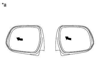 |
Turn the power switch on (IG).
Using the outer mirror switch assembly, turn the mirror surface to the fully left position.
Press the M1 switch while the SET switch is being pressed.
Check that the buzzer sounds for 0.5 seconds and the mirror surface position is memorized.
Using the outer mirror switch assembly, turn the mirror surface to the fully right position.
Press the M1 switch.
Check that the buzzer sounds for 0.1 seconds and the outer mirror automatically moves to the recorded fully left position.
| *a | Turn to Left Fully |
|
| ||||
| OK | ||
| ||
| ||
| 9.REPLACE OUTER MIRROR ACTUATOR ASSEMBLY LH |
Replace the outer mirror actuator assembly LH (Click here).
| NEXT | |
|
| 10.CHECK MEMORY AND REACTIVATION FUNCTION |
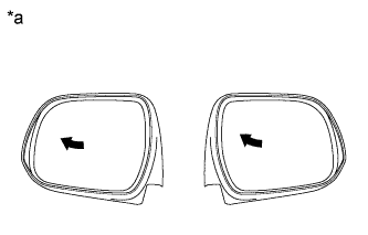 |
Turn the power switch on (IG).
Using the outer mirror switch assembly, turn the mirror surface to the fully left position.
Press the M1 switch while the SET switch is being pressed.
Check that the buzzer sounds for 0.5 seconds and the mirror surface position is memorized.
Using the outer mirror switch assembly, turn the mirror surface to the fully right position.
Press the M1 switch.
Check that the buzzer sounds for 0.1 seconds and the outer mirror automatically moves to the recorded fully left position.
| *a | Turn to Left Fully |
|
| ||||
| OK | ||
| ||
| ||


