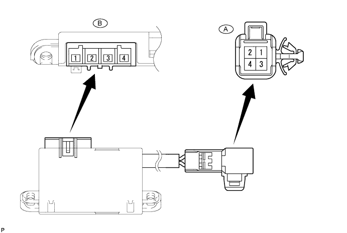
Terminal No. (Symbol)
| Terminal Description
| Condition
| Specified Condition
|
A-1 (CCU) - Body ground
| LED output signal
| Power switch on (IG), Outer mirror switch (Heated steering wheel switch) on
| Below 3 V
|
A-2 (CCV) - Body ground
| Steering heater switch input signal
| Power switch on (IG), Outer mirror switch (Heated steering wheel switch) pressed and held
| 11 to 14 V
|
A-3 (CCX) - Body ground
| Ground
| Always
| Below 1 Ω
|
A-4 (CCW) - Body ground
| IG power supply
| Power switch on (IG)
| 11 to 14 V
|
B-1 (TH1) - Body ground
| Thermistor input signal
| Power switch on (IG), Outer mirror switch (Heated steering wheel switch) on at 0 to 40°C (32 to 104°F)
| 1.5 to 4.5 V*1
|
B-2 (TH2) - Body ground
| Thermistor ground
| Power switch on (IG), Outer mirror switch (Heated steering wheel switch) on
| Below 1 V
|
B-3 (SH2) - Body ground
| Heater output signal
| Power switch on (IG), Outer mirror switch (Heated steering wheel switch) on
| 11 to 14 V*2
|
B-4 (SH1) - Body ground
| Heater ground
| Power switch on (IG), Outer mirror switch (Heated steering wheel switch) on
| Below 1 V
|