HEATED STEERING WHEEL SYSTEM > Steering Wheel does not Heat Up When Heated Steering Wheel Switch is Pressed |
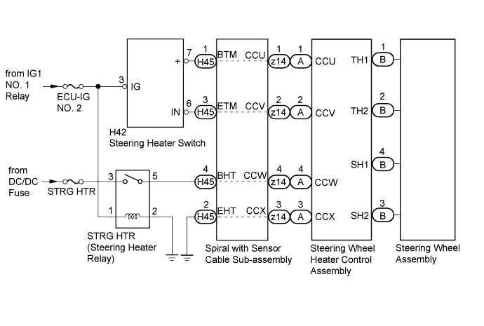
| 1.INSPECT STEERING WHEEL ASSEMBLY (THERMISTOR·HEATER·THERMOSTAT) |
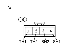 |
Disconnect the B steering wheel controller connector.
Measure the resistance according to the value(s) in the table below.
| Tester Connection | Condition | Specified Condition |
| B-1 (TH1) - B-2 (TH2) | 10 to 30°C (50 to 86°F) | 8.132 to 18.43 kΩ |
| B-4 (SH1) - B-3 (SH2) | 20°C (68°F) | 1.89 to 2.25 Ω |
| *a | Front view of wire harness connector (to Steering Wheel Control Assembly) |
|
| ||||
| OK | |
 |
| 2.INSPECT SPIRAL WITH SENSOR CABLE SUB-ASSEMBLY |
Check the connectors and cables of the spiral with sensor cable sub-assembly.
Disconnect the H45 and z14 spiral with sensor cable sub-assembly connectors.
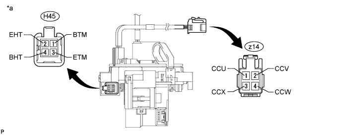
Disconnect the heated steering wheel controller connector.
Measure the resistance according to the value(s) in the table below.
| Tester Connection | Condition | Specified Condition |
| z14-1 (CCU) - H45-1 (BTM) | Always | Below 1 Ω |
| z14-2 (CCV) - H45-3 (ETM) | Always | Below 1 Ω |
| z14-3 (CCX) - H45-2 (EHT) | Always | Below 1 Ω |
| z14-4 (CCW) - H45-4 (BHT) | Always | Below 1 Ω |
| *a | Component without harness connected (Spiral with Sensor Cable Sub-assembly) | - | - |
|
| ||||
| OK | |
|
| 3.CHECK STEERING HEATER SWITCH |
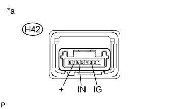 |
Disconnect the H42 steering heater switch connector.
Measure the voltage according to the value(s) in the table below.
| Tester Connection (Positive (+) tester probe - Negative (-) tester probe) | Condition | Specified Condition |
| H42-3 (IG) - H42-7 (+) | Always | Below 1.25 V |
| H42-6 (IN) - H42-7 (+) | Steering heater switch is pushed | Below 1.25 V |
Measure the resistance according to the value(s) in the table below.
| Tester Connection | Condition | Specified Condition |
| H42-3 (IG) - H42-6 (IN) | Steering heater switch is pushed | Below 1 Ω |
| H42-3 (IG) - H42-6 (IN) | Steering heater switch is not pushed | 10 kΩ or higher |
| *a | Component without harness connected (Steering Heater Switch) |
|
| ||||
| OK | |
|
| 4.CHECK STRG HTR RELAY (STEERING HEATER RELAY) |
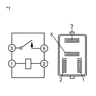 |
Remove the STRG HTR relay (steering heater relay).
Measure the resistance according to the value(s) in the table below.
| Tester Connection | Condition | Specified Condition |
| 3 - 5 | Voltage is not applied between terminals 1 and 2 | 10 kΩ or higher |
| 3 - 5 | Voltage is applied between terminals 1 and 2 | Below 1 Ω |
| *1 | STRG HTR Relay (Steering Heater Relay) |
|
| ||||
| OK | |
|
| 5.CHECK HARNESS AND CONNECTOR (STEERING HEATER SWITCH - SPIRAL W/ SENSOR CABLE SUB-ASSEMBLY) |
Disconnect the H42 steering heater switch connector.
Disconnect the H45 spiral with sensor cable sub-assembly connector.
Measure the resistance according to the value(s) in the table below.
| Tester Connection | Condition | Specified Condition |
| H42-7 (+) - H45-1 (BTM) | Always | Below 1 Ω |
| H42-6 (IN) - H45-3 (ETM) | Always | Below 1 Ω |
|
| ||||
| OK | |
|
| 6.CHECK HARNESS AND CONNECTOR (STRG HTR RELAY - SPIRAL WITH SENSOR CABLE SUB-ASSEMBLY) |
Remove the STRG HTR relay (steering heater relay) from the relay block No. 3.
Disconnect the H45 spiral with sensor cable sub-assembly connector.
Measure the resistance according to the value(s) in the table below.
| Tester Connection | Condition | Specified Condition |
| Relay block No. 3 - 5 - H45-4 (BHT) | Always | Below 1 Ω |
|
| ||||
| OK | |
|
| 7.CHECK HARNESS AND CONNECTOR (STEERING HEATER SWITCH POWER SOURCE) |
Disconnect the H42 steering heater switch connector.
Measure the voltage according to the value(s) in the table below.
| Tester Connection | Switch Condition | Specified Condition |
| H42-3 (IG) - Body ground | Power switch on (IG) | 11 to 14 V |
|
| ||||
| OK | |
|
| 8.CHECK HARNESS AND CONNECTOR (STRG HTR RELAY (STEERING HEATER RELAY) POWER SOURCE) |
Remove the STRG HTR relay (steering heater relay) from the relay block No. 3.
Measure the voltage according to the value(s) in the table below.
| Tester Connection | Condition | Specified Condition |
| Relay block No. 3-3 - Body ground | Always | 11 to 14 V |
| Relay block No. 3-1 - Body ground | Power switch on (IG) | 11 to 14 V |
Measure the resistance according to the value(s) in the table below.
| Tester Connection | Condition | Specified Condition |
| Relay block No. 3-2 - Body ground | Always | Below 1 Ω |
|
| ||||
| OK | |
|
| 9.CHECK HARNESS AND CONNECTOR (SPIRAL WITH SENSOR CABLE SUB-ASSEMBLY BODY GROUND) |
Disconnect the H45 spiral with sensor cable sub-assembly connector.
Measure the resistance according to the value(s) in the table below.
| Tester Connection | Condition | Specified Condition |
| H45-2 (EHT) - Body ground | Always | Below 1 Ω |
|
| ||||
| OK | ||
 | ||
| ||

