DTC U1110 Lost Communication with Clearance Sonar Module |
| DTC Code | DTC Detection Condition | Trouble Area |
| U1110 | No communication from clearance warning ECU assembly |
|
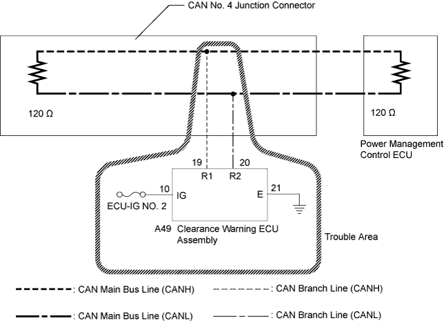
| 1.RECONFIRM DTC OUTPUT |
Reconfirm DTCs.
| Result | Proceed to |
| U1002 is not output from power management control ECU (Intelligent tester display/PM1 Gateway) | A |
| U1002 is output from power management control ECU (Intelligent tester display/PM1 Gateway) | B |
|
| ||||
| A | |
 |
| 2.CHECK CAN BUS LINE FOR DISCONNECTION (CLEARANCE WARNING ECU ASSEMBLY BRANCH LINE) |
Turn the power switch off.
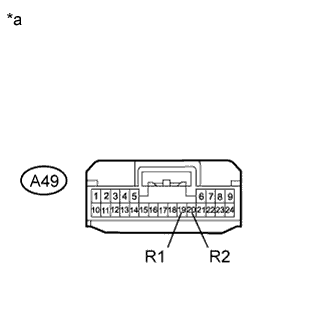 |
Disconnect the clearance warning ECU assembly connector.
Measure the resistance according to the value(s) in the table below.
| Tester Connection | Switch Condition | Specified Condition |
| A49-19 (R1) - A49-20 (R2) | Power switch off | 54 to 69 Ω |
| *a | Front view of wire harness connector (to Clearance Warning ECU Assembly) |
|
| ||||
| OK | |
|
| 3.CHECK HARNESS AND CONNECTOR (POWER SOURCE CIRCUIT) |
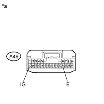 |
Measure the resistance according to the value(s) in the table below.
| Tester Connection | Condition | Specified Condition |
| A49-21 (E) - Body ground | Always | Below 1 Ω |
Measure the voltage according to the value(s) in the table below.
| Tester Connection | Switch Condition | Specified Condition |
| A49-10 (IG) - Body ground | Power switch on (IG) | 11 to 14 V |
| *a | Front view of wire harness connector (to Clearance Warning ECU Assembly) |
|
| ||||
| OK | ||
 | ||
| ||

