FRONT POWER SEAT CONTROL SYSTEM (w/ Memory) > Front Power Seat does not Operate with Front Power Seat Switch |
| 1.CHECK FRONT POWER SEAT OPERATION |
Check that each function of the power seat operates normally by using the power seat switch (Click here).
| Result | Proceed to |
| All power seat functions do not operate | A |
| One or more power seat functions do not operate | B |
|
| ||||
| A | |
 |
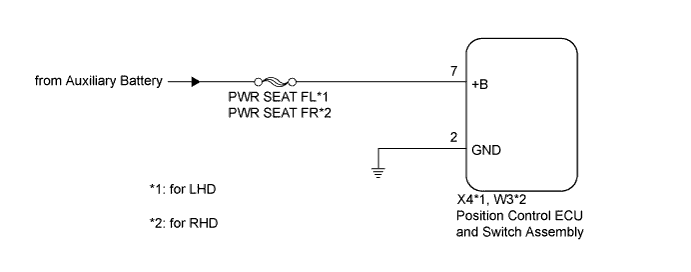
| 2.CHECK HARNESS AND CONNECTOR (POSITION CONTROL ECU AND SWITCH ASSEMBLY - BATTERY) |
Disconnect the X4*1 or W3*2 position control ECU and switch assembly connectors.
Measure the voltage according to the value(s) in the table below.
| Tester Connection | Condition | Specified Condition |
| X4-7 (+B) - Body ground | Power switch off | 11 to 14 V |
| Tester Connection | Condition | Specified Condition |
| W3-7 (+B) - Body ground | Power switch off | 11 to 14 V |
|
| ||||
| OK | |
|
| 3.CHECK HARNESS AND CONNECTOR (POSITION CONTROL ECU AND SWITCH ASSEMBLY - BODY GROUND) |
Measure the resistance according to the value(s) in the table below.
| Tester Connection | Condition | Specified Condition |
| X4-2 (GND) - Body ground | Always | Below 1 Ω |
| Tester Connection | Condition | Specified Condition |
| W3-2 (GND) - Body ground | Always | Below 1 Ω |
|
| ||||
| OK | ||
 | ||
| ||

