FRONT POWER SEAT CONTROL SYSTEM (w/ Memory) > Power Seat Position is not Memorized |
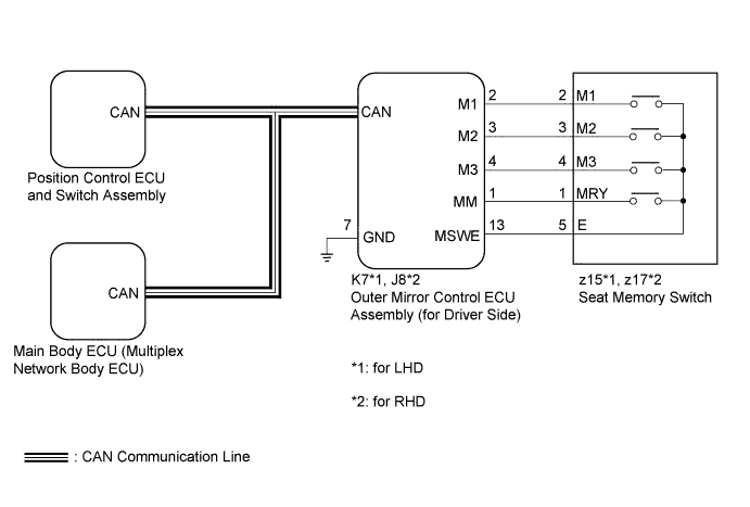
| 1.CHECK CAN COMMUNICATION SYSTEM |
Use the intelligent tester to check if the CAN communication system is functioning normally (Click here).
|
| ||||
| OK | |
 |
| 2.CHECK FRONT POWER SEAT CONTROL SYSTEM |
Check that each function of the power seat operates normally by using the power seat switch (Click here).
|
| ||||
| OK | |
|
| 3.READ VALUE USING INTELLIGENT TESTER (SEAT MEMORY SWITCH) |
Connect the intelligent tester to the DLC3.
Turn the power switch on (IG).
Turn the intelligent tester on.
Enter the following menus: Body / Mirror L*1 or Mirror R*2 / Data List
Read the Data List according to the display on the intelligent tester.
| Tester Display | Measurement Item/Range | Normal Condition | Diagnostic Note |
| SET Switch | SET switch signal / ON or OFF | ON: SET switch on OFF: SET switch off | - |
| M1 Switch | M1 switch signal / ON or OFF | ON: M1 switch on OFF: M1 switch off | - |
| M2 Switch | M2 switch signal / ON or OFF | ON: M2 switch on OFF: M2 switch off | - |
| M3 Switch | M3 switch signal / ON or OFF | ON: M3 switch on OFF: M3 switch off | - |
|
| ||||
| OK | |
|
| 4.PERFORM ACTIVE TEST USING INTELLIGENT TESTER (BUZZER) |
Connect the intelligent tester to the DLC3.
Turn the power switch on (IG).
Turn the intelligent tester on.
Enter the following menus: Body / Driver Seat / Data List.
Read the Data List according to the display on the intelligent tester.
| Tester Display | Test Part | Control Range | Diagnostic Note |
| Buzzer | Buzzer operation | ON / OFF | - |
|
| ||||
| OK | |
|
| 5.REPLACE OUTER MIRROR CONTROL ECU ASSEMBLY (for Driver Side) |
Replace the outer mirror control ECU assembly (for driver side) (Click here).
| NEXT | |
|
| 6.CHECK SEAT POSITION MEMORY FUNCTION |
Perform a memory operation and check that the buzzer sounds to indicate the completion of the memory operation (Click here).
|
| ||||
| OK | ||
 | ||
| ||
| 7.REPLACE POSITION CONTROL ECU AND SWITCH ASSEMBLY |
Replace the position control ECU and switch assembly (Click here).
| NEXT | |
|
| 8.CHECK SEAT POSITION MEMORY FUNCTION |
Perform a memory operation and check that the buzzer sounds to indicate the completion of the memory operation (Click here).
|
| ||||
| OK | ||
| ||
| ||
| 9.INSPECT SEAT MEMORY SWITCH |
Remove the seat memory switch (Click here).
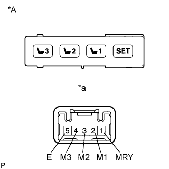 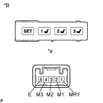 |
Measure the resistance according to the value(s) in the table below.
| Tester Connection | Switch Condition | Specified Condition |
| 1 (MRY) - 5 (E) | SET switch is pressed | Below 1 Ω |
| 2 (M1) - 5 (E) | M1 switch is pressed | Below 1 Ω |
| 3 (M2) - 5 (E) | M2 switch is pressed | Below 1 Ω |
| 4 (M3) - 5 (E) | M3 switch is pressed | Below 1 Ω |
| 1 (MRY) - 5 (E) | SET switch is not pressed | 10 kΩ or higher |
| 2 (M1) - 5 (E) | M1 switch is not pressed | 10 kΩ or higher |
| 3 (M2) - 5 (E) | M2 switch is not pressed | 10 kΩ or higher |
| 4 (M3) - 5 (E) | M3 switch is not pressed | 10 kΩ or higher |
| *A | for LHD |
| *B | for RHD |
| *a | Component without harness connected (Seat Memory Switch) |
|
| ||||
| OK | |
|
| 10.CHECK HARNESS AND CONNECTOR (OUTER MIRROR CONTROL ECU - SEAT MEMORY SWITCH) |
Disconnect the K7*1 or J8*2 outer mirror control ECU assembly (for driver side) connector.
Measure the resistance according to the value(s) in the table below.
| Tester Connection | Condition | Specified Condition |
| z15-1 (MRY) - K7-1 (MM) | Always | Below 1 Ω |
| z15-2 (M1) - K7-2 (M1) | Always | Below 1 Ω |
| z15-3 (M2) - K7-3 (M2) | Always | Below 1 Ω |
| z15-4 (M3) - K7-4 (M3) | Always | Below 1 Ω |
| z15-5 (E) - K7-13 (MSWE) | Always | Below 1 Ω |
| K7-7 (GND) - Body ground | Always | Below 1 Ω |
| K7-1 (MM) - Body ground | Always | 10 kΩ or higher |
| K7-2 (M1) - Body ground | Always | 10 kΩ or higher |
| K7-3 (M2) - Body ground | Always | 10 kΩ or higher |
| K7-4 (M3) - Body ground | Always | 10 kΩ or higher |
| K7-13 (MSWE) - Body ground | Always | 10 kΩ or higher |
| Tester Connection | Condition | Specified Condition |
| z17-1 (MRY) - J8-1 (MM) | Always | Below 1 Ω |
| z17-2 (M1) - J8-2 (M1) | Always | Below 1 Ω |
| z17-3 (M2) - J8-3 (M2) | Always | Below 1 Ω |
| z17-4 (M3) - J8-4 (M3) | Always | Below 1 Ω |
| z17-5 (E) - J8-13 (MSWE) | Always | Below 1 Ω |
| J8-7 (GND) - Body ground | Always | Below 1 Ω |
| J8-1 (MM) - Body ground | Always | 10 kΩ or higher |
| J8-2 (M1) - Body ground | Always | 10 kΩ or higher |
| J8-3 (M2) - Body ground | Always | 10 kΩ or higher |
| J8-4 (M3) - Body ground | Always | 10 kΩ or higher |
| J8-13 (MSWE) - Body ground | Always | 10 kΩ or higher |
|
| ||||
| OK | ||
| ||
| ||


