DTC B1500 Fuel Sender Open Detected |
| DTC No. | DTC Detection Condition | Trouble Area |
| B1500 | When IG voltage is 9.5 V or more and the following condition is detected:
|
|
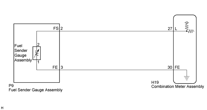
| 1.READ VALUE USING INTELLIGENT TESTER (FUEL INPUT) |
Connect the intelligent tester to the DLC3.
Turn the power switch on (IG).
Turn the intelligent tester on.
Enter the following menus: Body / Combination Meter / Data List.
Check the values by referring to the table below.
| Tester Display | Measurement Item/Range | Normal Condition | Diagnostic Note |
| Fuel Input | Fuel input signal/Min.: 0, Max.: 127.5 | Fuel indicates F: 39.6 | Unit: Liter |
| Fuel indicates 3/4: 31.0 | |||
| Fuel indicates 1/2: 22.8 | |||
| Fuel indicates 1/4: 14.3 | |||
| Fuel indicates E: 5.1 |
| Result | Proceed to |
| Fuel level data can be displayed on the intelligent tester and DTC B1500 is output. | A |
| Fuel level data cannot be displayed on the intelligent tester. | B |
|
| ||||
| A | ||
 | ||
| ||
| 2.INSPECT FUEL SENDER GAUGE ASSEMBLY |
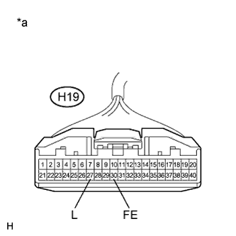 |
Disconnect the H19 connector.
Measure the resistance according to the value(s) in the table below.
| Tester Connection | Condition | Specified Condition |
| H19-27 (L) - H19-30 (FE) | Always | 12.0 to 415.0 Ω |
| *a | Front view of wire harness connector (to Combination Meter Assembly) |
|
| ||||
| OK | ||
| ||
| ||
| 3.CHECK HARNESS AND CONNECTOR (COMBINATION METER ASSEMBLY - FUEL SENDER GAUGE ASSEMBLY) |
Disconnect the P9 connector.
Measure the resistance according to the value(s) in the table below.
| Tester Connection | Condition | Specified Condition |
| H19-27 (L) - P9-2 (FS) | Always | Below 1 Ω |
| H19-27 (L) - Body ground | Always | 10 kΩ or higher |
| H19-30 (FE) - P9-3 (FE) | Always | Below 1 Ω |
| H19-30 (FE) - Body ground | Always | 10 kΩ or higher |
|
| ||||
| OK | |
 |
| 4.INSPECT FUEL SENDER GAUGE ASSEMBLY |
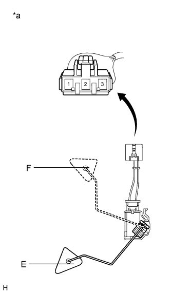 |
Remove the fuel sender gauge assembly (Click here).
Check that the float moves smoothly between E and F.
Measure the resistance according to the value(s) in the table below.
| Tester Connection | Condition | Specified Condition |
| 1 - 2 | Float level is F (upper) | 12 to 18 Ω |
| 1 - 2 | Float level is between F (upper) and E (lower) | 12 to 415 Ω (Gradually changes) |
| 1 - 2 | Float level is E (lower) | 405 to 415 Ω |
| *a | Front view of wire harness connector (to Fuel Sender Gauge Assembly) |
|
| ||||
| OK | ||
| ||
| ||


