AUDIO AND VISUAL SYSTEM (w/o Navigation System) > Mute Signal Circuit between Radio Receiver and Multi-media Interface ECU |
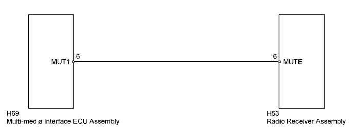
| 1.INSPECT RADIO RECEIVER ASSEMBLY |
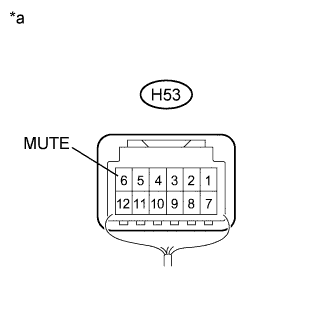 |
Measure the voltage according to the value(s) in the table below.
| Tester Connection | Condition | Specified Condition |
| H53-6 (MUTE) - Body ground | Power switch on (ACC), USB audio system is playing → Mode is changing | Above 2.5 V → Below 0.5 V |
| *a | Component with harness connected (Radio Receiver Assembly) |
|
| ||||
| OK | ||
 | ||
| ||
| 2.CHECK HARNESS AND CONNECTOR (RADIO RECEIVER ASSEMBLY - MULTI-MEDIA INTERFACE ECU ASSEMBLY) |
Disconnect the radio receiver assembly and multi-media interface ECU assembly connectors.
Measure the resistance according to the value(s) in the table below.
| Tester Connection | Condition | Specified Condition |
| H53-6 (MUTE) - H69-6 (MUT1) | Always | Below 1 Ω |
| H53-6 (MUTE) - Body ground | Always | 10 kΩ or higher |
|
| ||||
| OK | |
 |
| 3.INSPECT MULTI-MEDIA INTERFACE ECU ASSEMBLY |
Reconnect the multi-media interface ECU assembly connector.
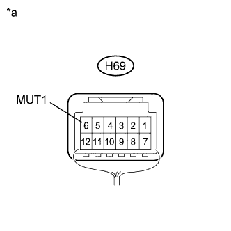 |
Measure the voltage according to the value(s) in the table below.
| Tester Connection | Condition | Specified Condition |
| H69-6 (MUT1) - Body ground | Power switch on (ACC) | Above 2.5 V |
| *a | Component with harness connected (Multi-media Interface ECU Assembly) |
|
| ||||
| OK | ||
| ||
| ||


