DTC B279A Theft Deterrent System Communication Line High Fixation |
| DTC Code | DTC Detection Condition | Trouble Area | DTC Output Confirmation Operation |
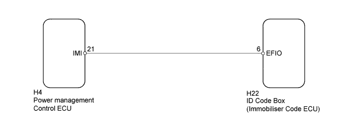
| B279A | The communication line (IMI - EFIO) between the power management control ECU and ID code box (immobiliser code ECU) is stuck high (1 trip detection logic*). |
| Turn the power switch on (IG) and wait 6 seconds. |
| Vehicle Condition when Malfunction Detected | Fail-safe Operation when Malfunction Detected |
| Hybrid control system cannot be started | Hybrid control system cannot be started |
| DTC Code | Data List and Active Test |
| B279A | - |
| 1.CLEAR DTC |
Clear the DTCs (Click here).
| NEXT | |
 |
| 2.CHECK FOR DTC |
Turn the power switch on (IG) and wait 10 seconds.
Check for DTCs (Click here).
| Result | Proceed to |
| DTC B279A is output | A |
| DTC B279A and other DTCs are output | B |
|
| ||||
| A | |
|
| 3.CHECK CONNECTION OF CONNECTOR |
Turn the power switch off.
Check that the connectors are properly connected to the power management control ECU and ID code box (immobiliser code ECU).
|
| ||||
| OK | |
|
| 4.CHECK HARNESS AND CONNECTOR (ID CODE BOX - POWER MANAGEMENT CONTROL ECU) |
Disconnect the H22 box connector.
Disconnect the H4 ECU connector.
Measure the resistance according to the value(s) in the table below.
| Tester Connection | Condition | Specified Condition |
| H22-6 (EFIO) - H4-21 (IMI) | Always | Below 1 Ω |
| H4-21 (IMI) - Body ground | Always | 10 kΩ or higher |
Measure the voltage according to the value(s) in the table below.
| Tester Connection | Condition | Specified Condition |
| H4-21 (IMI) - Body ground | Always | Below 1 V |
|
| ||||
| OK | |
|
| 5.REPLACE ID CODE BOX (IMMOBILISER CODE ECU) |
Replace the ID code box (immobiliser code ECU) with a new one.
| NEXT | |
|
| 6.CLEAR DTC |
Clear the DTCs (Click here).
| NEXT | |
|
| 7.REGISTER RECOGNITION CODES |
Register the recognition codes in the ECUs.
| NEXT | |
|
| 8.REGISTER ECU COMMUNICATION ID (ID CODE BOX - POWER MANAGEMENT CONTROL ECU) |
Register the ECU communication ID.
| NEXT | |
|
| 9.CHECK FOR DTC |
Check for DTCs (Click here).
|
| ||||
| OK | ||
 | ||
| ||

