METER / GAUGE SYSTEM > Speed Signal Circuit |
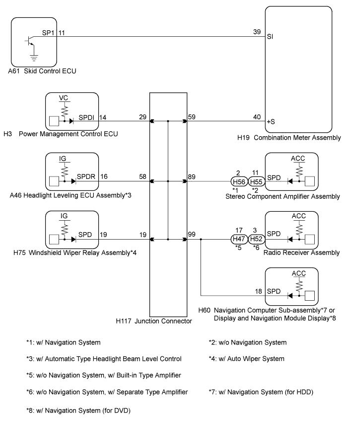
| 1.INSPECT ECU TERMINAL VOLTAGE (INPUT VOLTAGE) |
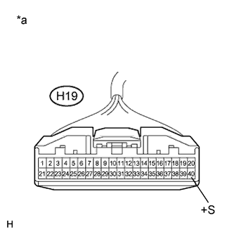 |
Disconnect the H19 connector.
Measure the voltage according to the value(s) in the table below.
| Tester Connection | Condition | Specified Condition |
| H19-40 (+S) - Body ground | Power switch on (IG) | 4.5 to 14 V |
| *a | Front view of wire harness connector (to Combination Meter Assembly) |
|
| ||||
| OK | |
 |
| 2.INSPECT COMBINATION METER ASSEMBLY (OUTPUT VOLTAGE) |
Reconnect the H19 connector.
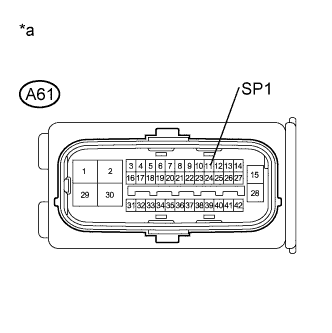 |
Disconnect the A61 connector.
Measure the voltage according to the value(s) in the table below.
| Tester Connection | Condition | Specified Condition |
| A61-11 (SP1) - Body ground | Power switch on (IG) | 11 to 14 V |
| *a | Front view of wire harness connector (to Skid Control ECU) |
|
| ||||
| OK | |
|
| 3.INSPECT SKID CONTROL ECU (INPUT WAVEFORM) |
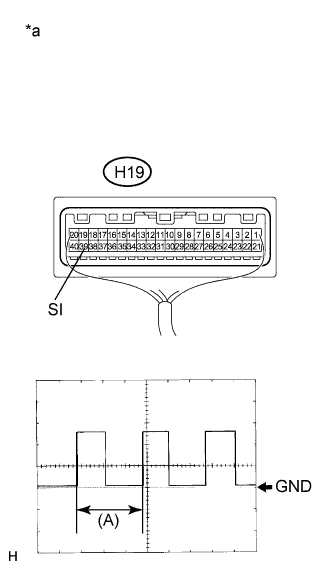 |
Check the input waveform.
Reconnect the A61 connector.
Remove the combination meter assembly with the connector(s) still connected.
Connect an oscilloscope to terminal H19-39 (SI) and body ground.
Turn the power switch on (IG).
Turn the wheel slowly.
Check the signal waveform according to the condition(s) in the table below.
| Item | Condition |
| Tool setting | 5 V/DIV., 20 ms/DIV. |
| Vehicle condition | Wheel being rotated |
| *a | Component with harness connected (Combination Meter Assembly) |
| Result | Proceed to |
| OK | A |
| NG (for LHD) | B |
| NG (for RHD) | C |
|
| ||||
|
| ||||
| A | ||
 | ||
| ||
| 4.CHECK HARNESS AND CONNECTOR (COMBINATION METER ASSEMBLY - SKID CONTROL ECU) |
Disconnect the H19 and A61 connectors.
Measure the resistance according to the value(s) in the table below.
| Tester Connection | Condition | Specified Condition |
| A61-11 (SP1) - H19-39 (SI) | Always | Below 1 Ω |
| A61-11 (SP1) - Body ground | Always | 10 kΩ or higher |
|
| ||||
| OK | ||
| ||
| ||
| 5.CHECK HARNESS AND CONNECTOR (COMBINATION METER ASSEMBLY - JUNCTION CONNECTOR) |
Disconnect the junction connector.
Measure the resistance according to the value(s) in the table below.
| Tester Connection | Condition | Specified Condition |
| H19-40 (+S) - H117-59 | Always | Below 1 Ω |
| H19-40 (+S) - Body ground | Always | 10 kΩ or higher |
|
| ||||
| OK | |
|
| 6.CHECK HARNESS AND CONNECTOR (JUNCTION CONNECTOR) |
Inspect for a short in the circuit that is connected to the junction block connector shown in the wiring diagram.
Disconnect the 3B connector.
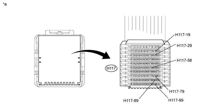
Measure the voltage according to the value(s) in the table below.
| Tester Connection | Condition | Specified Condition |
| H117-29 - Body ground | Power switch on (IG) | 4.5 to 14 V |
| H117-19 - Body ground | Power switch on (IG) | 4.5 to 14 V |
| H117-89 - Body ground | Power switch on (IG) | 4.5 to 14 V |
| H117-58 - Body ground | Power switch on (IG) | 4.5 to 14 V |
| H117-79 - Body ground | Power switch on (IG) | 4.5 to 14 V |
| H117-99 - Body ground | Power switch on (IG) | 4.5 to 14 V |
| *a | Front view of wire harness connector (to Junction Connector) |
| Result | Proceed to |
| Voltage is not present in one circuit. | A |
| Voltage is present in all the circuits. | B |
|
| ||||
| A | |
|
| 7.SYSTEM CHECK |
Select the circuit for which voltage was not present in step 6.
| Tester Connection | System that Uses the Circuit | Proceed to |
| H117-29 - Body ground | Hybrid Control System | A |
| H117-19 - Body ground | Wiper and Washer System*1 | B |
| H117-58 - Body ground | Lighting System*2 | C |
| H117-89 - Body ground | Audio/Visual System | D |
| H117-99 - Body ground | Audio/Visual System | D |
| H117-99 - Body ground | Navigation System*3 or *4 | D |
|
| ||||
|
| ||||
|
| ||||
| A | |
|
| 8.CHECK HARNESS AND CONNECTOR (POWER MANAGEMENT CONTROL ECU CIRCUIT) |
Disconnect the H3 connector.
Measure the resistance according to the value(s) in the table below.
| Tester Connection | Condition | Specified Condition |
| H3-14 (SPDI) - Body ground | Always | 10 kΩ or higher |
|
| ||||
| OK | ||
| ||
| ||
| 9.CHECK HARNESS AND CONNECTOR (WINDSHIELD WIPER RELAY ASSEMBLY CIRCUIT) |
Disconnect the H75 connector.
Measure the resistance according to the value(s) in the table below.
| Tester Connection | Condition | Specified Condition |
| H75-19 (SPD) - Body ground | Always | 10 kΩ or higher |
|
| ||||
| OK | ||
| ||
| ||
| 10.CHECK HARNESS AND CONNECTOR (HEADLIGHT LEVELING ECU ASSEMBLY CIRCUIT) |
Disconnect the A46 connector.
Measure the resistance according to the value(s) in the table below.
| Tester Connection | Condition | Specified Condition |
| A46-16 (SPDR) - Body ground | Always | 10 kΩ or higher |
| Result | Proceed to |
| OK (for LHD) | A |
| OK (for RHD) | B |
| NG | C |
|
| ||||
|
| ||||
| A | ||
| ||
| ||
| 11.SYSTEM CHECK |
Select the circuit for which voltage was not present in step 6.
| Tester Connection | System that Uses the Circuit | Proceed to |
| H117-89 - Body ground | Audio/Visual System | A |
| H117-99 - Body ground | Audio/Visual System | B |
| H117-99 - Body ground | Navigation System*1 or *2 | B |
|
| ||||
| A | |
|
| 12.CHECK HARNESS AND CONNECTOR (STEREO COMPONENT AMPLIFIER ASSEMBLY CIRCUIT) |
Disconnect the H56*1 or H55*2 connector.
Measure the resistance according to the value(s) in the table below.
| Tester Connection | Condition | Specified Condition |
| H56-2 (SPD)*1 - Body ground | Always | 10 kΩ or higher |
| H55-11 (SPD)*2 - Body ground | Always | 10 kΩ or higher |
|
| ||||
| OK | ||
| ||
| ||
| 13.CHECK HARNESS AND CONNECTOR (RADIO RECEIVER CIRCUIT, NAVIGATION RECEIVER CIRCUIT) |
Disconnect the H47*1, H52*2, or H60*3 connector.
Measure the resistance according to the value(s) in the table below.
| Tester Connection | Condition | Specified Condition |
| H47-17 (SPD)*1 - Body ground | Always | 10 kΩ or higher |
| H52-3 (SPD)*2 - Body ground | Always | 10 kΩ or higher |
| H60-18 (SPD)*3 - Body ground | Always | 10 kΩ or higher |
| Result | Proceed to |
| OK (w/o Navigation System) | A |
| OK (w/ Navigation System (for HDD)) | B |
| OK (w/ Navigation System (for DVD)) | C |
| NG | D |
|
| ||||
|
| ||||
|
| ||||
| A | ||
| ||
| ||


