WIRELESS DOOR LOCK CONTROL SYSTEM > Only Wireless Control Function is Inoperative |
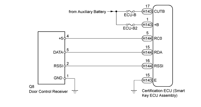
| 1.SYSTEM CHECK |
Check the vehicle specification.
| Result | Proceed to |
| w/o Entry Function | A |
| w/ Entry Function | B |
|
| ||||
| A | |
 |
| 2.INSPECT AUXILIARY BATTERY VOLTAGE |
Measure the voltage of the auxiliary battery with the power switch off.
| NEXT | |
|
| 3.CHECK FOR DTC |
Open the driver door using the mechanical key built into the electrical key transmitter.
Connect the intelligent tester and check for DTCs (Click here).
|
| ||||
| OK | |
|
| 4.CHECK POWER DOOR LOCK CONTROL SYSTEM |
When the door control switch on the multiplex network master switch assembly on the driver door is operated, check that the doors unlock and lock according to the switch operation (Click here).
|
| ||||
| OK | |
|
| 5.CHECK ELECTRICAL KEY TRANSMITTER |
When a known good registered electrical key transmitter is used, check that the wireless functions operate normally.
| Result | Proceed to |
| Wireless door LOCK/UNLOCK function operates normally with a known good electrical key transmitter. | A |
| Wireless door LOCK/UNLOCK function does not operate | B |
|
| ||||
| A | |
|
| 6.CHECK ELECTRICAL KEY TRANSMITTER (LED) |
Press and hold the lock switch of the electrical key transmitter for 5 seconds and check the number of times that the electrical key transmitter LED illuminates.
| Result | Proceed to |
| Electrical key transmitter LED does not illuminate when switch is pressed and held | A |
| Electrical key transmitter LED illuminates 3 times or more when switch is pressed and held | B |
| Electrical key transmitter LED illuminates once or twice but not third time | C |
|
| ||||
|
| ||||
| A | |
|
| 7.INSPECT TRANSMITTER BATTERY (VOLTAGE) |
Inspect the transmitter battery (for Type A)
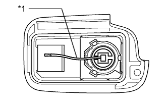 |
Remove the battery from the electrical key transmitter that does not operate (Click here).
Attach a lead wire (0.60 mm [0.0236 in.] in diameter or less including wire sheath) with tape or equivalent to the negative terminal.
| *1 | Lead Wire |
Carefully pull the lead wire out from the position shown in the illustration and install the previously removed transmitter battery.
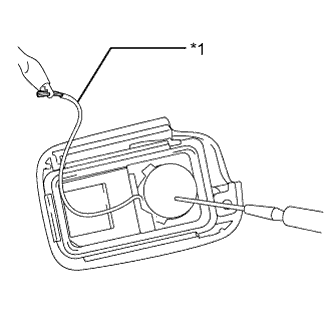 |
Measure the voltage of the transmitter battery.
| *1 | GND |
| Tester Connection | Condition | Specified Condition |
| Transmitter battery positive (+) - Transmitter battery negative (-) | Power switch off, all doors closed and LOCK or UNLOCK switch is pressed | 2.2 to 3.2 V |
Inspect the transmitter battery (for Type B)
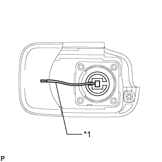 |
Remove the battery from the electrical key transmitter that does not operate (Click here).
Attach a lead wire (0.60 mm [0.0236 in.] in diameter or less including wire sheath) with tape or equivalent to the negative terminal.
| *1 | Lead Wire |
Carefully pull the lead wire out from the position shown in the illustration and install the previously removed transmitter battery.
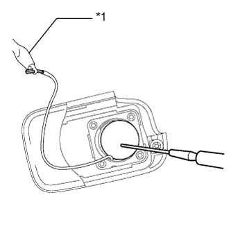 |
Measure the voltage of the transmitter battery.
| *1 | GND |
| Tester Connection | Condition | Specified Condition |
| Transmitter battery positive (+) - Transmitter battery negative (-) | Power switch off, all doors closed and LOCK or UNLOCK switch is pressed | 2.2 to 3.2 V |
|
| ||||
| OK | ||
 | ||
| ||
| 8.CHECK WAVE ENVIRONMENT |
Bring the electrical key transmitter near the door control receiver and perform a wireless function operation check.
|
| ||||
| OK | ||
| ||
| ||
| 9.CHECK POWER SOURCE |
When the power switch is off, check that the functions other than the wireless functions recognize the power source mode as being off.
|
| ||||
| OK | |
|
| 10.CHECK HARNESS AND CONNECTOR (CERTIFICATION ECU - BATTERY AND BODY GROUND) |
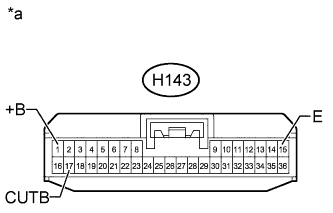 |
Disconnect the H143 ECU connector.
Measure the voltage according to the value(s) in the table below.
| Tester Connection | Condition | Specified Condition |
| H143-17 (CUTB) - Body ground | IG OFF | 11 to 14 V |
| H143-1 (+B) - Body ground | IG OFF | 11 to 14 V |
Measure the resistance according to the value(s) in the table below.
| Tester Connection | Condition | Specified Condition |
| H143-15 (E) - Body ground | Always | Below 1 Ω |
| *a | Front view of wire harness connector (to Certification ECU (smart key ECU assembly)) |
|
| ||||
| OK | |
|
| 11.CHECK HARNESS AND CONNECTOR (DOOR CONTROL RECEIVER - CERTIFICATION ECU AND BODY GROUND) |
Disconnect the Q8 door control receiver connector.
Disconnect the H144 certification ECU (smart key ECU assembly) connector.
Measure the resistance according to the value(s) in the table below.
| Tester Connection | Condition | Specified Condition |
| Q8-4 (+5) - H144-5 (RCO) | Always | Below 1 Ω |
| Q8-5 (DATA) - H144-15 (RDA) | Always | Below 1 Ω |
| Q8-2 (RSSI) - H144-16 (RSSI) | Always | Below 1 Ω |
| Q8-1 (GND) - Body ground | Always | Below 1 Ω |
| Q8-4 (+5) or H144-5 (RCO) - Body ground | Always | 10 kΩ or higher |
| Q8-5 (DATA) or H144-15 (RDA) - Body ground | Always | 10 kΩ or higher |
| Q8-2 (RSSI) or H144-16 (RSSI) - Body ground | Always | 10 kΩ or higher |
|
| ||||
| OK | |
|
| 12.CHECK DOOR CONTROL RECEIVER (OPERATION) |
Temporarily replace the door control receiver with a new or normally functioning one (Click here).
Check that the wireless functions operate normally.
|
| ||||
| OK | ||
| ||
| ||


