BRAKE PEDAL (for LHD) > ADJUSTMENT |
| 1. INSPECT AND ADJUST BRAKE PEDAL HEIGHT |
Check the brake pedal height.
Turn back the carpet.
Turn back the dash silencer from the slit provided on the dash silencer.
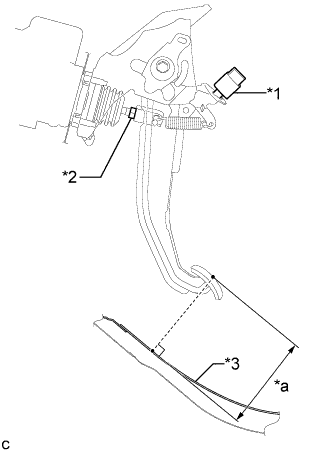 |
Measure the shortest distance between the brake pedal surface and floor panel.
| *1 | Stop Light Switch Assembly |
| *2 | Clevis Lock Nut |
| *3 | Floor Panel |
| *a | Brake Pedal Height |
| Brake Pedal | Specified Value |
| w/o Aluminum Pedal | 126.8 to 136.8 mm (4.99 to 5.39 in.) |
| w/ Aluminum Pedal | 128.8 to 138.8 mm (5.07 to 5.46 in.) |
Adjust the brake pedal height.
Remove the stop light switch assembly (Click here).
Loosen the clevis lock nut.
Adjust the brake pedal height by turning the push rod.
Tighten the clevis lock nut.
Install and adjust the stop light switch assembly (Click here).
| 2. INSPECT AND ADJUST BRAKE PEDAL STROKE SENSOR ASSEMBLY |
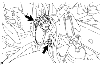 |
Loosen the 2 nuts.
Connect the intelligent tester to the DLC3.
Turn the power switch on (IG).
Turn the intelligent tester on.
Enter the following menus: Chassis / ABS/VSC/TRC / Data List "Stroke Sensor".
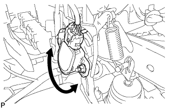 |
Read the stroke sensor value in the Data List, and turn the brake pedal stroke sensor assembly slowly to the right or left to adjust the output voltage so that it is within the following range.
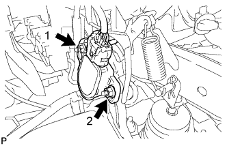 |
Tighten the 2 nuts.
Turn the power switch off.
Disconnect the intelligent tester.
| 3. INSPECT BRAKE PEDAL FREE PLAY |
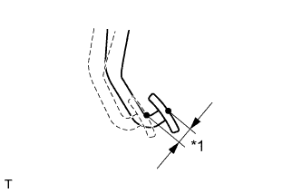 |
Depress the pedal until a slight resistance is felt. Measure the brake pedal free play as shown in the illustration.
| *1 | Brake Pedal Free Play |
| 4. INSPECT BRAKE PEDAL RESERVE DISTANCE |
Release the parking brake.
With the power switch on (READY), depress the brake pedal and measure the pedal reserve distance.
| Brake Pedal | Specified Value |
| w/o Aluminum Pedal | More than 77.0 mm (3.03 in.) |
| w/ Aluminum Pedal | More then 79.0 mm (3.11 in.) |
| 5. PERFORM INITIALIZATION AND CALIBRATION OF LINEAR SOLENOID VALVE |
