BRAKE PEDAL (for LHD) > INSTALLATION

for Preparation Click here


1. INSTALL BRAKE PEDAL PAD


2. INSTALL BRAKE PEDAL SUPPORT ASSEMBLY
  1. Install the nut to the brake pedal support assembly.

  1. Install the brake pedal support assembly with the 4 nuts.

    Torque:
    13 N*m{ 130 kgf*cm , 9 ft.*lbf }

  1. Engage the clamp.

  1. Install the brake pedal support assembly to the instrument panel reinforcement with the bolt.

    Torque:
    24 N*m{ 241 kgf*cm , 17 ft.*lbf }


3. INSTALL PUSH ROD PIN
  1. Apply lithium soap base glycol grease to the push rod pin and installation hole of the brake pedal sub-assembly.

  1. Install the push rod pin and a new clip to connect the push rod clevis to the brake pedal sub-assembly.


4. INSTALL BRAKE PEDAL RETURN SPRING
  1. Install the brake pedal return spring to the brake pedal support assembly and push rod pin.


5. INSTALL STOP LIGHT SWITCH MOUNTING ADJUSTER


6. INSTALL STOP LIGHT SWITCH ASSEMBLY


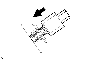
    E167768
  1. Insert the stop light switch assembly until the rod hits the pedal.
    NOTICE:
    When inserting the stop light switch assembly, support the pedal from behind so that the pedal is not pushed in.


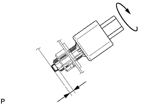
    E167769
  1. Make a quarter turn clockwise to install the stop light switch assembly.

    Torque:
    1.5 N*m{ 15 kgf*cm , 13 in.*lbf } or less

    NOTICE:
    When inserting the stop light switch assembly, support the pedal from behind so that the pedal is not pushed in.

  1. Connect the connector.

  1. Check the protrusion of the rod.

    Protrusion of the rod:
    1.5 to 2.5 mm (0.0591 to 0.0984 in.)

    If the protrusion is not as specified, adjust it.

    NOTICE:
    Do not depress the brake pedal.


7. INSTALL BRAKE PEDAL STROKE SENSOR ASSEMBLY

NOTICE:
  1. Do not drop the brake pedal stroke sensor assembly.
  2. If the brake pedal stroke sensor assembly has been dropped, replace the brake pedal stroke sensor assembly with a new one.


  1. When installing a new brake pedal stroke sensor assembly:
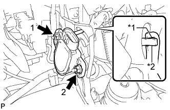
    NOTICE:
    Do not break the brake pedal stroke sensor assembly lever set pin before installing the brake pedal stroke sensor assembly with the nut.


      C233736E01
    1. Install a new brake pedal stroke sensor assembly to the brake pedal support assembly with the 2 nuts.
      Text in Illustration 
      *1
      Brake Pedal Groove
      *2
      Brake Pedal Stroke Sensor Assembly Lever

      Torque:
      7.0 N*m{ 71 kgf*cm , 62 in.*lbf }

      NOTICE:
      1. Engage the brake pedal stroke sensor assembly lever with the brake pedal groove.
      2. Check that there is no foreign matter attached to the contact surface of the brake pedal stroke sensor assembly.
      3. Check that the tip of the brake pedal stroke sensor assembly lever is protruding from the brake pedal groove.
      4. Tighten the 2 nuts in the order shown in the illustration.

    2. Connect the connector.

    3. Firmly depress the brake pedal and break the brake pedal stroke sensor assembly lever set pin.

    4. Remove the broken lever set pin.


  1. When reusing the brake pedal stroke sensor assembly:
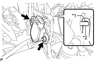


      C233736E02
    1. Temporarily install the brake pedal stroke sensor assembly to the brake pedal support assembly with the 2 nuts.
      Text in Illustration 
      *1
      Brake Pedal Groove
      *2
      Brake Pedal Stroke Sensor Assembly Lever

      NOTICE:
      1. Engage the brake pedal stroke sensor assembly lever with the brake pedal groove.
      2. Check that there is no foreign matter attached to the contact surface of the brake pedal stroke sensor assembly.
      3. Check that the tip of the brake pedal stroke sensor assembly lever is protruding from the brake pedal groove.

    2. Connect the connector.


8. INSTALL POWER STEERING ECU ASSEMBLY
(Click here)


9. INSTALL LOWER NO. 1 INSTRUMENT PANEL AIRBAG ASSEMBLY
(Click here)


10. INSPECT AND ADJUST BRAKE PEDAL
(Click here)


11. PERFORM INITIALIZATION AND CALIBRATION OF LINEAR SOLENOID VALVE
(Click here)