BRAKE BOOSTER (for RHD) > INSTALLATION |
| 1. INSTALL BRAKE BOOSTER GASKET |
Install a new brake booster gasket to the brake booster with master cylinder assembly.
| 2. INSTALL BRAKE BOOSTER WITH MASTER CYLINDER ASSEMBLY |
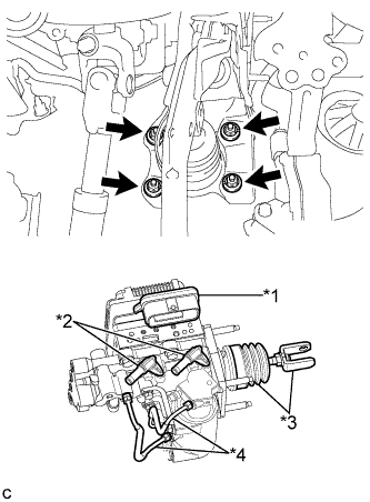 |
Install the brake booster with master cylinder assembly with the 4 nuts.
| *1 | Connector Portion |
| *2 | Union |
| *3 | Push Rod Clevis and Boot |
| *4 | Front No. 2 Brake Tube |
Engage the grommet of the brake line.
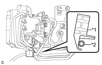 |
Set the brake line to the clamp as shown in the illustration.
| *1 | Clamp |
| *2 | Brake Line |
Using a union nut wrench, connect the brake line to the front flexible hose RH.
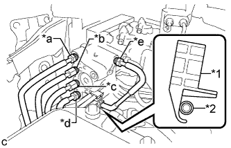 |
Using a union nut wrench, connect each brake line to the brake booster with master cylinder assembly as shown in the illustration.
| *1 | Clamp |
| *2 | Brake Line |
| *a | to Front Wheel Cylinder LH |
| *b | to Rear Wheel Cylinder RH |
| *c | to Brake Booster Pump Assembly |
| *d | to Rear Wheel Cylinder LH |
| *e | to Front Wheel Cylinder RH |
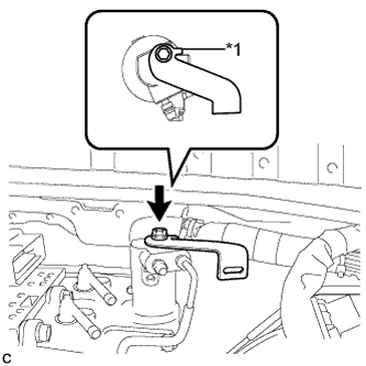 |
Install the wire harness clamp bracket to the brake booster with master cylinder assembly with the bolt.
| *1 | Stopper |
Connect the connector.
Engage the clamp.
| 3. CONNECT RESERVOIR TUBE ASSEMBLY |
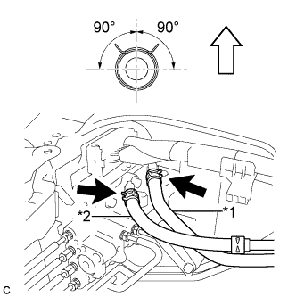 |
Connect the No. 1 reservoir hose and No. 2 reservoir hose with the clips.
| *1 | No. 1 Reservoir Hose |
| *2 | No. 2 Reservoir Hose |
 | Top of Vehicle |
| Identification Mark Color | Connection Color | |
| No. 1 Reservoir Hose | White | White (Unpainted) |
| No. 2 Reservoir Hose | Green | Green |
| 4. SEPARATE BRAKE MASTER CYLINDER RESERVOIR WITH BRACKET |
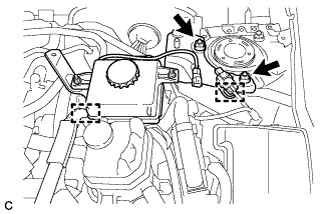 |
Disengage the 2 clamps.
Remove the 2 nuts and separate the brake master cylinder reservoir with bracket.
| 5. BLEED RESERVOIR TUBE ASSEMBLY |
Add brake fluid into the reservoir.
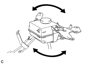 |
Lift up the brake master cylinder reservoir assembly as far as possible and rock it back and forth to bleed air from the reservoir tube assembly.
| 6. INSTALL BRAKE MASTER CYLINDER RESERVOIR WITH BRACKET |
Install the brake master cylinder reservoir with bracket with the 2 nuts.
Engage the 2 clamps.
| 7. INSTALL RESERVOIR TUBE ASSEMBLY |
Install the reservoir tube assembly with the 2 bolts and nut.
| 8. INSTALL PUSH ROD PIN |
Apply lithium soap base glycol grease to the push rod pin and installation hole of the brake pedal support assembly.
Install the push rod pin and a new clip to connect the push rod clevis to the brake pedal support assembly.
| 9. INSTALL BRAKE PEDAL RETURN SPRING |
Install the brake pedal return spring to the brake pedal support assembly and push rod pin.
| 10. FILL RESERVOIR WITH BRAKE FLUID |
| 11. CONNECT CABLE TO NEGATIVE AUXILIARY BATTERY TERMINAL |
| 12. BLEED BRAKE SYSTEM |
Remove the outer cowl top panel sub-assembly.
Bleed the brake system.
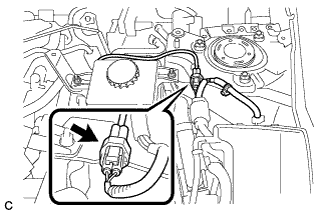 |
Wait at least 2 minutes with the power switch off, and disconnect the reservoir level switch connector.
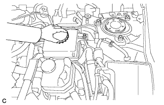 |
Remove the brake master cylinder reservoir filler cap assembly.
Add brake fluid into the reservoir between MAX and MIN level on the brake fluid reservoir.
Connect the intelligent tester to the DLC3 and turn the power switch on (IG).
Turn the intelligent tester on and enter the following menus: Chassis / ABS/VSC/TRC / Air Bleeding.
Select "ABS actuator has been replaced" on the intelligent tester display, and bleed air from the brake fluid following the instructions on the intelligent tester.
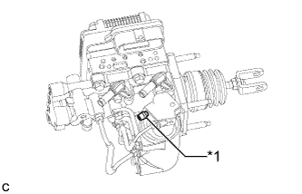 |
After air bleeding, tighten each bleeder plug.
| *1 | Stroke Simulator Bleeder Plug |
Clear the DTCs (Click here).
Turn the intelligent tester off and turn the power switch off.
Install the brake master cylinder reservoir filler cap.
Inspect for brake fluid leaks.
Install the outer cowl top panel sub-assembly.
| 13. INSPECT AND ADJUST BRAKE PEDAL |
| 14. OBTAIN ZERO POINT OF YAW RATE AND ACCELERATION SENSOR |
| 15. INSTALL NO. 1 INSTRUMENT PANEL UNDER COVER SUB-ASSEMBLY |
Connect each connector.
Engage the clamp.
Engage the 2 clips.
Install the No. 1 instrument panel under cover sub-assembly with the screw <E>.
| 16. INSTALL SUSPENSION TOWER DAMPER (w/ Suspension Tower Damper) |
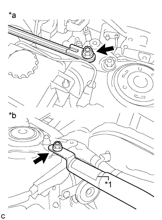 |
Install the suspension tower damper with the 2 nuts.
| *1 | Label |
| *a | LH Side |
| *b | RH Side |
| 17. INSTALL OUTER COWL TOP PANEL SUB-ASSEMBLY |
Install the outer cowl top panel sub-assembly with the 9 bolts.
w/ Wiper Deicer:
Engage the 3 clamps to install the wire harness.
Engage the clamp to install the wire harness.
| 18. INSTALL COWL BODY MOUNTING REINFORCEMENT RH |
Install the cowl body mounting reinforcement RH with the 2 bolts.
| 19. INSTALL NO. 2 HEATER AIR DUCT SPLASH SHIELD SEAL |
Engage the claw and guide to install the No. 2 heater air duct splash shield seal.
| 20. INSTALL NO. 1 HEATER AIR DUCT SPLASH SHIELD SEAL |
Engage the 2 claws to install the No. 1 heater air duct splash shield seal.
| 21. INSTALL WINDSHIELD WIPER MOTOR AND LINK ASSEMBLY |
