BRAKE BOOSTER (for LHD) > REMOVAL |
| 1. PRECAUTION |
| 2. DISABLE BRAKE CONTROL |
Wait at least 2 minutes after the power switch off.
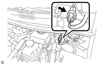 |
Disconnect the reservoir level switch connector with the parking brake applied.
Disconnect the cable from the negative (-) auxiliary battery terminal (Click here).
Depress the brake pedal 40 times or more to return all the fluid in the accumulator back to the reservoir.
Check that the brake pedal can not be further depressed.
Release the parking brake.
| 3. REMOVE WINDSHIELD WIPER MOTOR AND LINK ASSEMBLY |
| 4. REMOVE NO. 1 HEATER AIR DUCT SPLASH SHIELD SEAL |
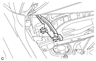 |
Disengage the 2 claws and remove the No. 1 heater air duct splash shield seal.
| 5. REMOVE NO. 2 HEATER AIR DUCT SPLASH SHIELD SEAL |
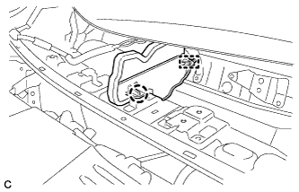 |
Disengage the claw and guide, and remove the No. 2 heater air duct splash shield seal.
| 6. REMOVE COWL BODY MOUNTING REINFORCEMENT LH |
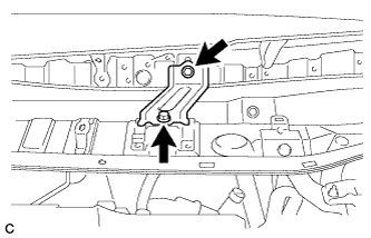 |
Remove the 2 bolts and cowl body mounting reinforcement LH.
| 7. REMOVE OUTER COWL TOP PANEL SUB-ASSEMBLY |
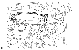 |
Disengage the clamp and separate the wire harness.
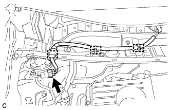 |
w/ Wiper Deicer:
Disengage the 3 clamps, disconnect the connector and separate the wire harness.
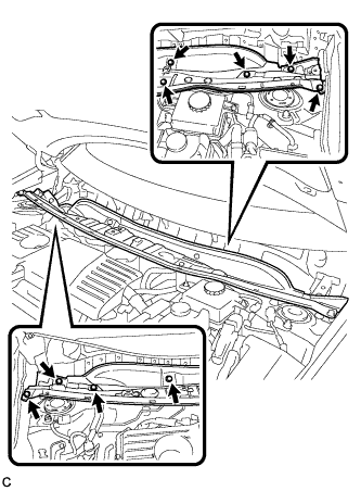 |
Remove the 9 bolts and outer cowl top panel sub-assembly.
| 8. REMOVE SUSPENSION TOWER DAMPER (w/ Suspension Tower Damper) |
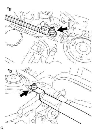 |
Remove the 2 nuts and the suspension tower damper from the vehicle.
| *a | LH Side |
| *b | RH Side |
| 9. DRAIN BRAKE FLUID |
| 10. REMOVE NO. 1 INSTRUMENT PANEL UNDER COVER SUB-ASSEMBLY |
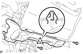 |
Remove the 2 screws <E>.
Disengage the clip.
Disengage the clamp.
Disconnect each connector and remove the No. 1 instrument panel under cover sub-assembly.
| 11. REMOVE BRAKE PEDAL RETURN SPRING |
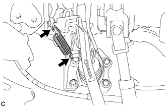 |
Remove the brake pedal return spring from the brake pedal support assembly and push rod pin.
| 12. REMOVE PUSH ROD PIN |
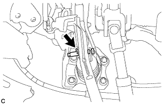 |
Remove the clip and push rod pin to separate the brake pedal sub-assembly from the push rod clevis.
| 13. SEPARATE BRAKE MASTER CYLINDER RESERVOIR WITH BRACKET |
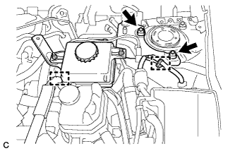 |
Disengage the 2 clamps.
Remove the 2 nuts and separate the brake master cylinder reservoir with bracket.
| 14. DISCONNECT RESERVOIR HOSE |
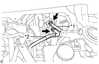 |
Move the 2 clips and disconnect the No. 1 reservoir hose and No. 2 reservoir hose from the brake booster with master cylinder assembly.
| *1 | No. 1 Reservoir Hose |
| *2 | No. 2 Reservoir Hose |
| 15. DISCONNECT BRAKE ACTUATOR HOSE |
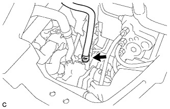 |
Move the clip and disconnect the brake actuator hose from the brake booster pump assembly.
| 16. REMOVE BRAKE MASTER CYLINDER RESERVOIR WITH BRACKET |
| 17. REMOVE NO. 5 BRAKE ACTUATOR BRACKET |
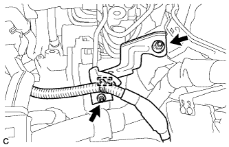 |
Disengage the clamp.
Remove the 2 nuts and No. 5 brake actuator bracket.
| 18. REMOVE BRAKE BOOSTER WITH MASTER CYLINDER ASSEMBLY |
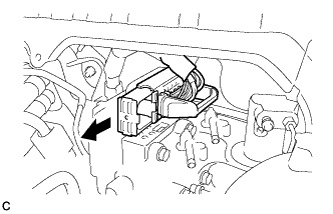 |
Release the lock lever and disconnect the connector from the brake booster with master cylinder assembly.
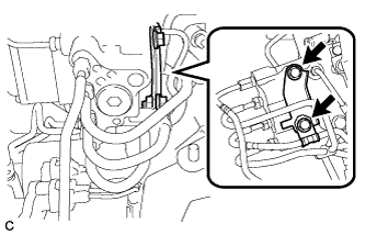 |
Remove the 2 bolts and No. 2 brake tube clamp bracket from the brake booster with master cylinder assembly.
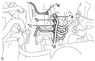 |
Using a union nut wrench, disconnect the 5 brake lines from the brake booster with master cylinder assembly.
Use tags or make a memo to identify the places to reconnect.
| *a | to Front Wheel Cylinder LH |
| *b | to Rear Wheel Cylinder RH |
| *c | to Brake Booster Pump Assembly |
| *d | to Rear Wheel Cylinder LH |
| *e | to Front Wheel Cylinder RH |
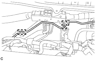 |
Disengage the 2 clamps and separate the brake line.
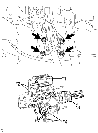 |
Remove the 4 nuts and brake booster with master cylinder assembly.
| *1 | Connector Portion |
| *2 | Union |
| *3 | Push Rod Clevis and Boot |
| *4 | Front No. 2 Brake Tube |
| 19. REMOVE BRAKE BOOSTER GASKET |
