HYBRID VEHICLE TRANSAXLE > REMOVAL |
| 1. PRECAUTION |
| 2. REMOVE REAR NO. 2 FLOOR BOARD |
Remove the rear No. 2 floor board.
| 3. REMOVE REAR DECK FLOOR BOX |
Remove the rear deck floor box.
| 4. REMOVE REAR NO. 3 FLOOR BOARD |
Remove the rear No. 3 floor board.
| 5. REMOVE DECK FLOOR BOX RH |
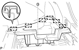 |
Remove the clip.
Disengage the 6 guides and remove the deck floor box RH.
| 6. REMOVE REAR FLOOR BOARD UPPER NO. 3 PLATE |
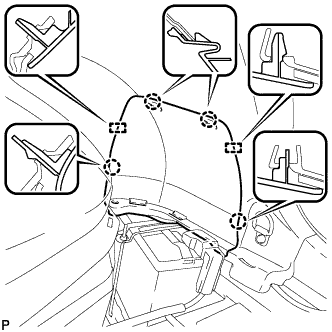 |
Disengage the 4 claws and 2 guides, and remove the rear floor board upper No. 3 plate.
| 7. DISCONNECT CABLE FROM NEGATIVE AUXILIARY BATTERY TERMINAL |
| 8. REMOVE SERVICE PLUG GRIP |
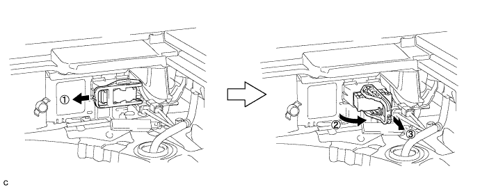
Wear insulated gloves and remove the service plug grip after sliding up the lever of the service plug grip as shown in the illustration.
| 9. REMOVE HOOD SUB-ASSEMBLY |
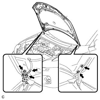 |
Disconnect the clamp and washer hose.
Remove the 4 bolts and hood sub-assembly.
| 10. ALIGN FRONT WHEELS FACING STRAIGHT AHEAD |
| 11. REMOVE FRONT WHEEL |
| 12. REMOVE REAR ENGINE UNDER COVER LH |
| 13. REMOVE REAR ENGINE UNDER COVER RH |
| 14. REMOVE FRONT LOWER BUMPER ABSORBER |
| 15. REMOVE NO. 1 ENGINE UNDER COVER |
| 16. DRAIN COOLANT (for Engine) |
Loosen the radiator drain cock plug.
Remove the reserve tank cap and drain the coolant.
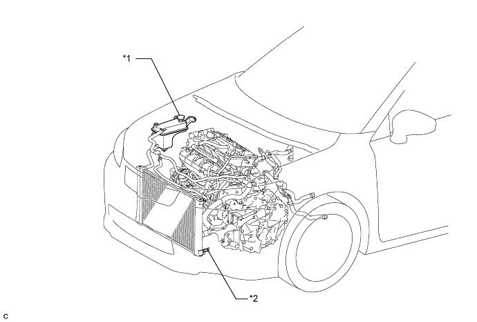
| *1 | Reserve Tank Cap | *2 | Radiator Drain Cock Plug |
| 17. DRAIN COOLANT (for Inverter) |
Remove the reserve tank cap.
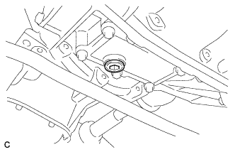 |
Using a hexagon wrench (10 mm), remove the drain plug indicated in the illustration and drain the coolant.
Install the plug with a new gasket.
| 18. DRAIN HYBRID TRANSAXLE FLUID |
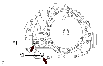 |
Using a 10 mm hexagon socket wrench, remove the filler plug and gasket.
| *1 | Filler Plug |
| *2 | Drain Plug |
Using a 10 mm hexagon socket wrench, remove the drain plug and gasket.
Using a 10 mm hexagon socket wrench, install the drain plug and a new gasket.
| 19. REMOVE WINDSHIELD WIPER MOTOR AND LINK ASSEMBLY |
| 20. REMOVE NO. 1 HEATER AIR DUCT SPLASH SHIELD SEAL (for LHD) |
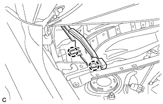 |
Disengage the 2 claws and remove the No. 1 heater air duct splash shield seal.
| 21. REMOVE NO. 1 HEATER AIR DUCT SPLASH SHIELD SEAL (for RHD) |
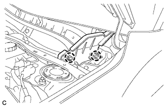 |
Disengage the 2 claws and remove the No. 1 heater air duct splash shield seal.
| 22. REMOVE NO. 2 HEATER AIR DUCT SPLASH SHIELD SEAL (for LHD) |
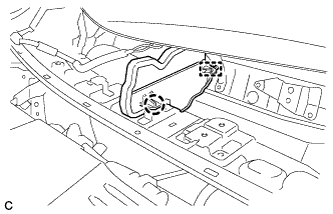 |
Disengage the claw and guide, and remove the No. 2 heater air duct splash shield seal.
| 23. REMOVE NO. 2 HEATER AIR DUCT SPLASH SHIELD SEAL (for RHD) |
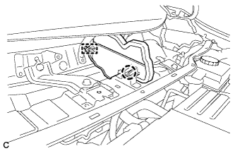 |
Disengage the claw and guide, and remove the No. 2 heater air duct splash shield seal.
| 24. REMOVE COWL BODY MOUNTING REINFORCEMENT LH (for LHD) |
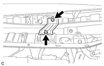 |
Remove the 2 bolts and cowl body mounting reinforcement LH.
| 25. REMOVE COWL BODY MOUNTING REINFORCEMENT RH (for RHD) |
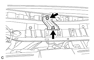 |
Remove the 2 bolts and cowl body mounting reinforcement RH.
| 26. REMOVE OUTER COWL TOP PANEL SUB-ASSEMBLY (for LHD) |
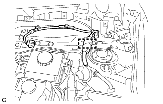 |
Disengage the clamp and separate the wire harness.
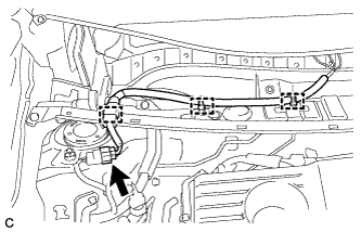 |
w/ Wiper Deicer:
Disengage the 3 clamps, disconnect the connector and separate the wire harness.
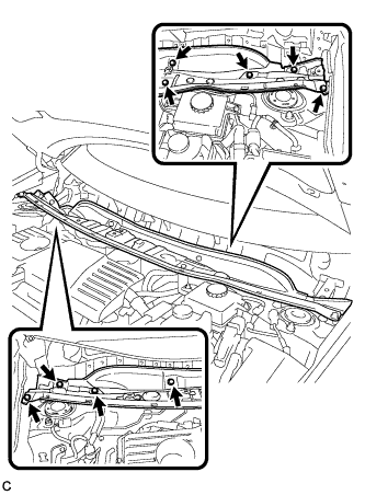 |
Remove the 9 bolts and outer cowl top panel sub-assembly.
| 27. REMOVE OUTER COWL TOP PANEL SUB-ASSEMBLY (for RHD) |
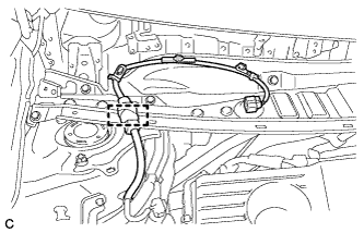 |
Disengage the clamp and separate the wire harness.
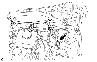 |
w/ Wiper Deicer:
Disengage the 3 clamps, disconnect the connector and separate the wire harness.
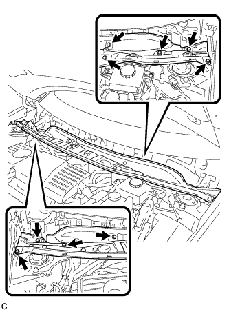 |
Remove the 9 bolts and outer cowl top panel sub-assembly.
| 28. REMOVE SUSPENSION TOWER DAMPER |
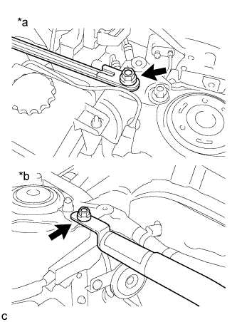 |
Remove the 2 nuts and the suspension tower damper from the vehicle.
| *a | LH Side |
| *b | RH Side |
| 29. REMOVE NO. 2 CYLINDER HEAD COVER |
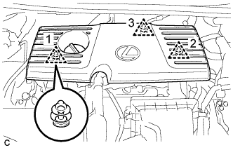 |
Remove the 3 clips and No. 2 cylinder head cover.
| 30. REMOVE AIR CLEANER CAP SUB-ASSEMBLY |
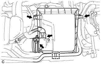 |
Disconnect the air flow meter connector.
Separate the water by-pass hose from the air cleaner cap sub-assembly.
Disconnect the 2 clamps and hose band, and remove the air cleaner cap sub-assembly.
Remove the air cleaner filter element sub-assembly.
| 31. REMOVE INLET AIR CLEANER |
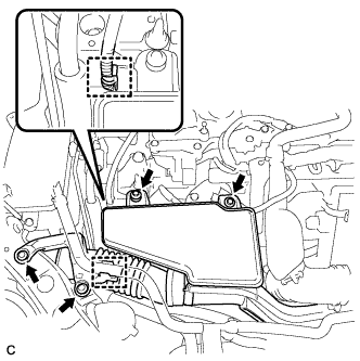 |
Separate the water by-pass hose from the inlet air cleaner.
Separate the wire harness clamp from the inlet air cleaner.
Remove the 2 bolts, 2 clips and inlet air cleaner.
| 32. REMOVE AIR CLEANER CASE |
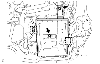 |
Separate the No. 4 water by-pass hose from the air cleaner case.
Disconnect the wire harness clamp from the air cleaner case.
Remove the 2 bolts and air cleaner case.
| 33. REMOVE AIR CLEANER HOSE ASSEMBLY |
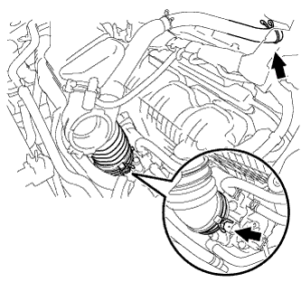 |
Loosen the hose clamp and separate the ventilation hose.
Unlock the hose clamp and remove the air cleaner hose assembly.
| 34. REMOVE INVERTER COVER ASSEMBLY LH (w/ Cover) |
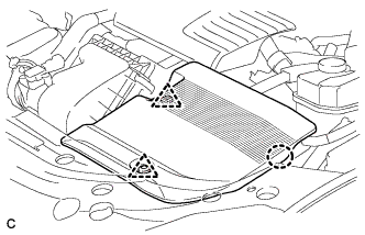 |
Remove the 2 clips
Disengage the claw and remove the inverter cover assembly LH.
| 35. REMOVE RADIATOR SUPPORT OPENING COVER |
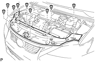 |
Remove the 9 clips and radiator support opening cover.
| 36. REMOVE NO. 1 INVERTER BRACKET |
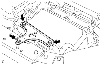 |
Remove the 3 bolts and No. 1 inverter bracket.
| 37. DISCONNECT ENGINE ROOM MAIN WIRE |
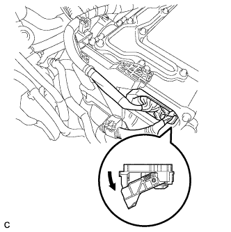 |
Raise the lock lever and disconnect the inverter with converter connector.
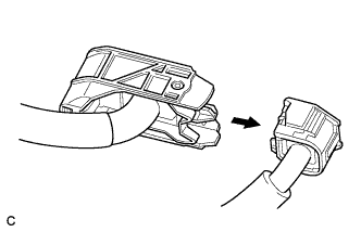 |
Disconnect the engine wire from the engine room main wire.
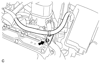 |
Remove the bolt.
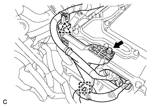 |
Remove the bolt, clamp and clip, and disconnect the engine room main wire.
| 38. REMOVE INVERTER COVER |
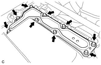 |
Remove the 9 bolts and inverter cover.
| 39. CHECK TERMINAL VOLTAGE |
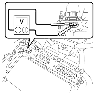 |
Using a voltmeter, measure the voltage between the terminals of the 2 phase connectors.
| 40. DISCONNECT FRAME WIRE |
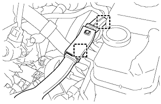 |
Disconnect the 2 harness clamps.
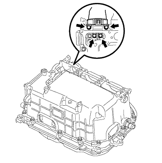 |
Remove the 4 bolts, and disconnect the frame wire (high voltage cables of the hybrid battery) from the inverter with converter assembly.
| 41. DISCONNECT GENERATOR CABLE |
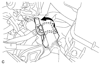 |
Turn back the wire harness cover and release the cable.
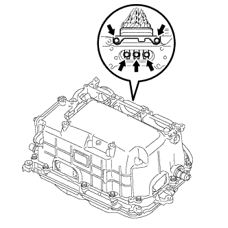 |
Remove the 5 bolts, and disconnect the high voltage cables of the generator cable (MG1) from the inverter with converter assembly.
| 42. DISCONNECT MOTOR CABLE |
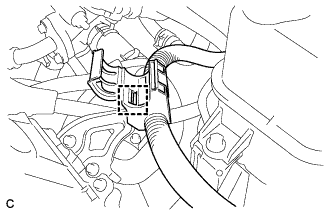 |
Disconnect the harness clamp.
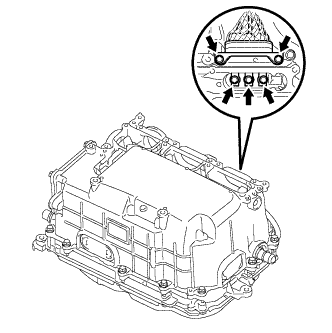 |
Remove the 5 bolts, and disconnect the high voltage cables of the motor cable (MG2) from the inverter with converter assembly.
| 43. DISCONNECT NO. 2 ENGINE WIRE |
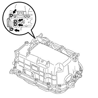 |
Remove the 4 bolts, and disconnect the No. 2 engine wire (high voltage cables for the air conditioning compressor) from the inverter with converter assembly.
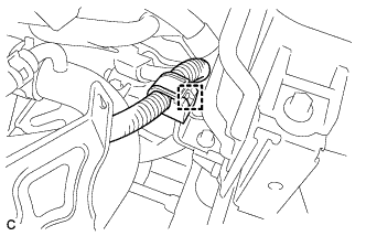 |
Disconnect the harness clamp.
| 44. INSTALL INVERTER COVER |
|
Temporarily install the inverter cover with the 9 bolts to prevent any foreign objects or water from entering the inverter with converter assembly.
| 45. DISCONNECT NO. 2 ENGINE ROOM WIRE |
Remove the relay block cover.
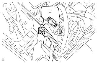 |
Release the 2 clamps, and remove the No. 1 relay block cover.
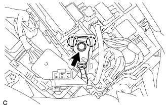 |
Remove the bolt from the No. 2 engine room wire.
Release the 2 claws, and disconnect the No. 2 engine room wire.
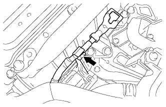 |
Connect the No. 2 engine room wire to the protector.
| 46. DISCONNECT WATER HOSE |
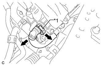 |
Release the retainer and disconnect the water hose from the inverter with converter assembly.
| *1 | Retainer |
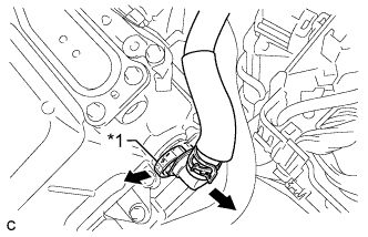 |
Release the retainer and disconnect the water hose from the inverter with converter assembly.
| *1 | Retainer |
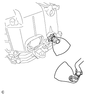 |
Disconnect the coolant hose from the inverter with converter assembly. Put a piece of cloth in the pipe and in the disconnected hose or cover the pipe and hose with plastic bags as shown in the illustration, so that foreign matter doesn't stick to the union or the inside of the connector and to prevent coolant from spilling near the inverter with converter assembly.
| 47. REMOVE INVERTER WITH CONVERTER ASSEMBLY |
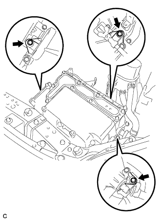 |
Remove the 3 bolts and inverter with converter assembly.
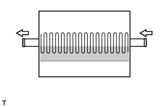 |
Even after the coolant is drained, coolant remains in the inverter due to its internal structure. Therefore, seal or cover the pipes when removing the inverter so that coolant does not spill out.
| 48. REMOVE INVERTER RESERVE TANK ASSEMBLY |
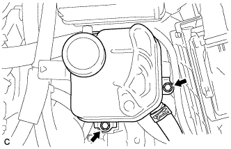 |
Remove the 2 bolts and separate the inverter reserve tank assembly.
| 49. REMOVE INVERTER TRAY BRACKET |
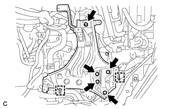 |
Separate the 2 clamps.
Remove the 5 bolts and inverter tray bracket.
| 50. DISCONNECT NO. 1 RADIATOR HOSE |
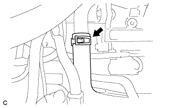 |
Disconnect the No. 1 radiator hose from the radiator pipe assembly.
| 51. DISCONNECT NO. 4 WATER BY-PASS HOSE |
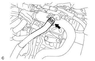 |
Disconnect the No. 4 water by-pass hose from the radiator pipe assembly.
| 52. REMOVE RADIATOR PIPE |
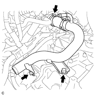 |
Separate the No. 3 radiator hose from the cylinder head.
Remove the 2 bolts and radiator pipe.
| 53. DISCONNECT NO. 3 INVERTER COOLING HOSE |
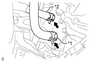 |
Disconnect the No. 3 inverter cooling hose from the hybrid transaxle assembly.
| *1 | No. 3 Inverter Cooling Hose |
| *2 | No. 5 Inverter Cooling Hose |
| 54. DISCONNECT NO. 5 INVERTER COOLING HOSE |
Disconnect the No. 5 inverter cooling hose from the hybrid transaxle assembly.
| 55. DISCONNECT WIRE HARNESS |
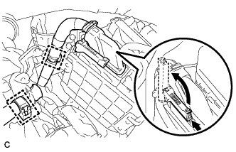 |
Disconnect the 2 clamps.
Pull up the lever and disconnect the connector of the ECM.
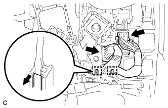 |
Remove the 2 connectors and 2 clamps from the engine room junction block and disconnect the wire harness.
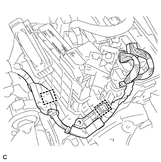 |
Disconnect the 2 clamps.
 |
Release the green-colored lock and disconnect the connector as shown in the illustration.
| *a | Green-colored Lock |
Remove the 2 bolts and disconnect the 6 connectors and 12 wire harness clamps.
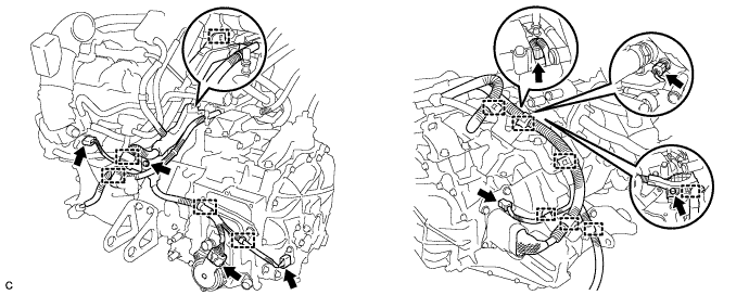
| 56. SECURE STEERING WHEEL |
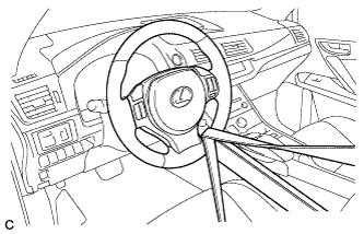 |
Secure the steering wheel with the seat belt in order to prevent rotation.
| 57. REMOVE COLUMN HOLE COVER SILENCER SHEET |
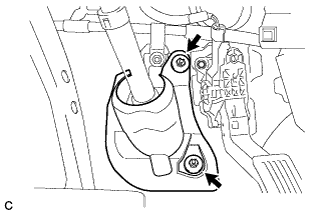 |
Turn back the floor carpet.
Remove the 2 clips and column hole cover silencer sheet.
| 58. SEPARATE NO. 2 STEERING INTERMEDIATE SHAFT ASSEMBLY |
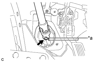 |
Put matchmarks on the No. 2 steering intermediate shaft assembly and steering intermediate shaft.
| *a | Matchmark |
Remove the bolt.
Separate the No. 2 steering intermediate shaft assembly from the steering intermediate shaft.
| 59. SEPARATE NO. 1 STEERING COLUMN HOLE COVER SUB-ASSEMBLY |
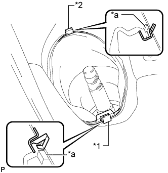 |
Remove clip A, detach clip B from the body and disconnect the No. 1 steering column hole cover sub-assembly.
| *1 | Clip A |
| *2 | Clip B |
| *a | Lip |
| 60. REMOVE FRONT NO. 3 ENGINE UNDER COVER |
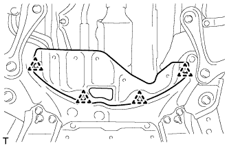 |
Remove the 4 clips and front No. 3 engine under cover.
| 61. REMOVE FRONT CENTER FLOOR BRACE |
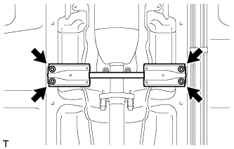 |
Remove the 4 bolts and front center floor brace.
| 62. REMOVE FRONT EXHAUST PIPE ASSEMBLY (w/ Exhaust Heat Recirculation System) |
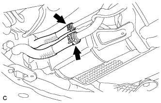 |
Disconnect the 2 heater water hoses.
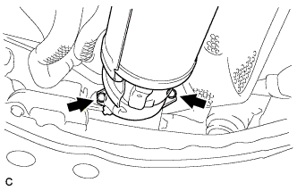 |
Remove the 2 bolts and 2 compression springs.
Remove the front exhaust pipe assembly from the 2 exhaust pipe supports.
Remove the gasket from the exhaust manifold.
| 63. REMOVE FRONT EXHAUST PIPE ASSEMBLY (w/o Exhaust Heat Recirculation System) |
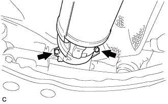 |
Remove the 2 bolts and 2 compression springs.
Remove the front exhaust pipe assembly from the 2 exhaust pipe supports.
Remove the gasket from the exhaust manifold.
| 64. REMOVE FRONT AXLE SHAFT NUT LH |
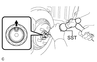 |
Using SST and a hammer, release the staked part of the front axle shaft nut.
While applying the brakes, remove the front axle shaft nut.
| 65. REMOVE FRONT AXLE SHAFT NUT RH |
| 66. SEPARATE FRONT SPEED SENSOR LH |
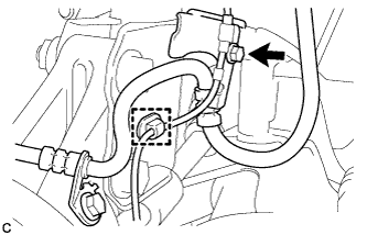 |
Remove the bolt and clamp, and separate the front speed sensor and front flexible hose from the front shock absorber with coil spring.
| 67. SEPARATE FRONT SPEED SENSOR RH |
| 68. SEPARATE TIE ROD END SUB-ASSEMBLY LH |
Remove the clip and nut.
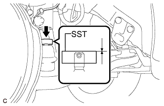 |
Install SST to the tie rod end.
Secure SST using a string.
Using SST, separate the tie rod end from the steering knuckle.
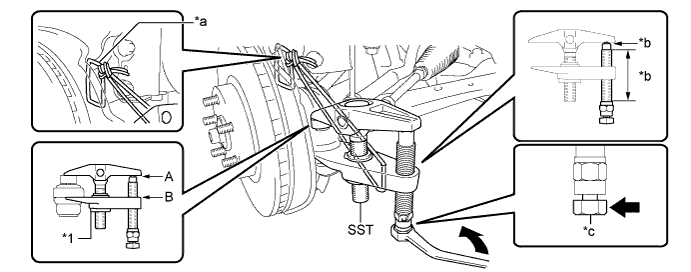
| *1 | Center Nut | - | - |
| *a | String | *b | Grease Application Area |
| *c | Place the wrench here. | - | - |
| 69. SEPARATE TIE ROD END SUB-ASSEMBLY RH |
| 70. SEPARATE FRONT STABILIZER LINK ASSEMBLY LH |
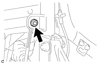 |
Remove the nut and separate the front stabilizer link assembly from the front shock absorber with coil spring.
| 71. SEPARATE FRONT STABILIZER LINK ASSEMBLY RH |
| 72. SEPARATE FRONT LOWER NO. 1 SUSPENSION ARM SUB-ASSEMBLY LH |
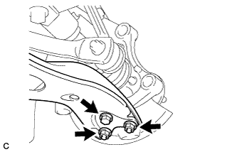 |
Remove the bolt and 2 nuts, and separate the front lower No. 1 suspension arm sub-assembly from the front lower ball joint assembly.
| 73. SEPARATE FRONT LOWER NO. 1 SUSPENSION ARM SUB-ASSEMBLY RH |
| 74. SEPARATE FRONT DRIVE SHAFT ASSEMBLY LH |
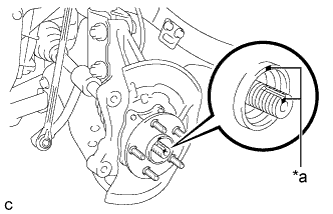 |
Put matchmarks on the front drive shaft assembly and front axle hub sub-assembly.
| *a | Matchmark |
Using a plastic hammer, separate the front drive shaft assembly from the front axle assembly. If it is difficult to separate, tap the end of the front drive shaft assembly using a brass bar and a hammer.
| 75. REMOVE FRONT DRIVE SHAFT ASSEMBLY LH |
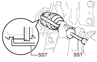 |
Using SST, remove the front drive shaft assembly.
| 76. SEPARATE FRONT DRIVE SHAFT ASSEMBLY RH |
| 77. REMOVE FRONT DRIVE SHAFT ASSEMBLY RH |
| 78. REMOVE FRONT DRIVE SHAFT HOLE SNAP RING LH |
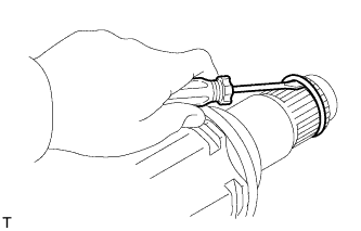 |
Using a screwdriver, remove the front drive shaft hole snap ring.
| 79. REMOVE FRONT DRIVE SHAFT HOLE SNAP RING RH |
| 80. INSTALL ENGINE HANGERS |
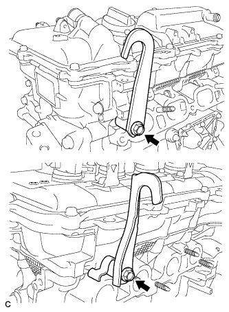 |
Install the 2 engine hangers with the 2 bolts.
| Part Name | Part No. |
| No. 1 engine hanger | 12281-37021 |
| No. 2 engine hanger | 12282-37011 |
| Bolt | 91552-81050 |
Attach a sling device to the engine hangers and a chain block.
| 81. REMOVE STARTER HOLE INSULATOR |
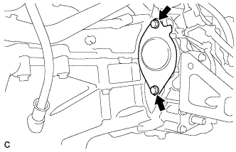 |
Remove the 2 bolts and starter hole insulator.
| 82. REMOVE FLYWHEEL HOUSING SIDE COVER |
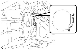 |
Remove the flywheel housing side cover.
| 83. REMOVE FRONT ENGINE MOUNTING BRACKET LOWER REINFORCEMENT |
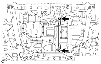 |
Remove the 2 bolts and front engine mounting bracket lower reinforcement.
| 84. REMOVE REAR SIDE RAIL REINFORCEMENT SUB-ASSEMBLY LH |
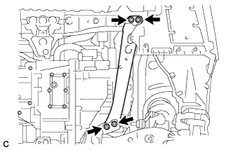 |
Remove the 4 bolts and rear side rail reinforcement sub-assembly LH.
| 85. REMOVE REAR SIDE RAIL REINFORCEMENT SUB-ASSEMBLY RH |
| 86. REMOVE FRONT SUSPENSION MEMBER REAR BRACE LH |
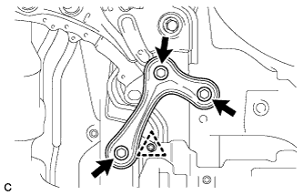 |
Remove the 3 bolts, clip and front suspension member rear brace LH.
| 87. REMOVE FRONT SUSPENSION MEMBER REAR BRACE RH |
| 88. REMOVE FRONT SUSPENSION CROSSMEMBER SUB-ASSEMBLY |
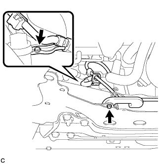 |
Remove the 2 bolts and 2 wiring harness clamp brackets from the front suspension crossmember sub-assembly.
Remove the 2 bolts and 2 nuts, and separate the front suspension crossmember sub-assembly from the rear engine mounting insulator.
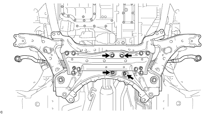
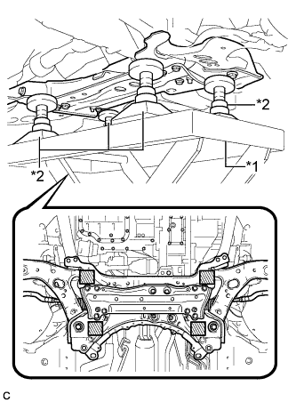 |
Support the front suspension crossmember sub-assembly with an engine lifter using 4 attachments or equivalent tools as shown in the illustration.
| *1 | Engine Lifter |
| *2 | Attachment |
 | Attachment placement location |
Remove the 2 bolts and front suspension crossmember sub-assembly.
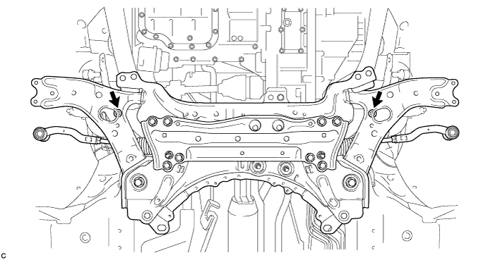
Slowly lower the front suspension crossmember sub-assembly.
| 89. REMOVE REAR ENGINE MOUNTING INSULATOR |
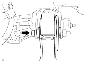 |
Remove the through bolt, and separate the rear engine mounting insulator.
| 90. SUPPORT HYBRID VEHICLE TRANSAXLE ASSEMBLY |
Support the hybrid vehicle transaxle assembly with a transmission jack.
| 91. REMOVE FRONT CROSSMEMBER SUB-ASSEMBLY |
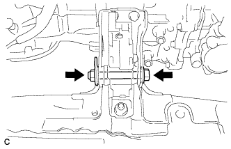 |
Remove the bolt and nut.
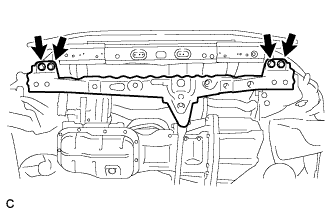 |
Remove the 4 bolts and front crossmember sub-assembly.
| 92. REMOVE FRONT ENGINE MOUNTING INSULATOR |
 |
Remove the 2 bolts and front engine mounting insulator.
| 93. REMOVE ENGINE MOUNTING BRACKET LH |
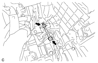 |
Remove the bolt and nut, and separate the engine mounting insulator LH.
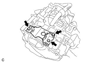 |
Remove the 3 bolts and engine mounting bracket LH.
| 94. REMOVE HYBRID VEHICLE TRANSAXLE ASSEMBLY |
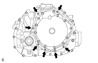 |
Remove the 7 bolts and hybrid vehicle transaxle assembly.
| 95. REMOVE FRONT ENGINE MOUNTING BRACKET |
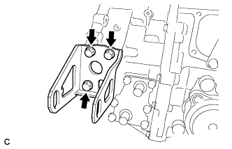 |
Remove the 3 bolts and front engine mounting bracket.
| 96. REMOVE REAR ENGINE MOUNTING BRACKET |
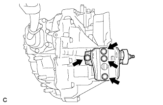 |
Remove the 4 bolts and rear engine mounting bracket.
| 97. REMOVE WIRE HARNESS CLAMP BRACKET |
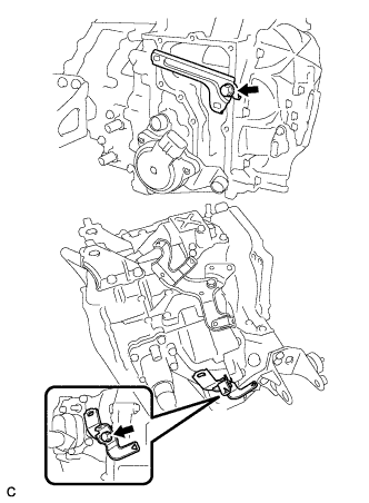 |
Remove the 2 bolts and 2 wire harness clamp brackets.
| 98. REMOVE MOTOR CABLE BRACKET |
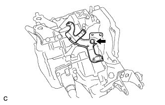 |
Remove the bolt and motor cable bracket.
