CYLINDER HEAD > INSPECTION |
| 1. INSPECT CYLINDER HEAD FOR FLATNESS |
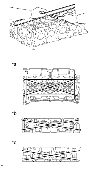 |
Using a precision straightedge and feeler gauge, measure the warpage of the contact surfaces where the cylinder head contacts the cylinder block and manifold.
| *a | Cylinder Head Lower Side: |
| *b | Intake Manifold Side: |
| *c | Exhaust Manifold Side: |
| Item | Specified Condition |
| Cylinder block side | 0.05 mm (0.00197 in.) |
| Intake manifold side | 0.10 mm (0.00394 in.) |
| Exhaust manifold side | 0.10 mm (0.00394 in.) |
| 2. INSPECT CYLINDER HEAD FOR CRACKS |
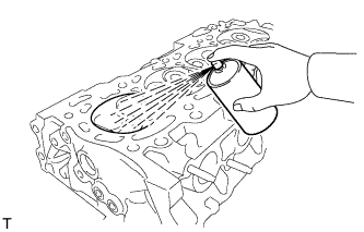 |
Using a dye penetrate, check the intake ports, exhaust ports and cylinder surface for cracks.
If cracked, replace the cylinder head.
| 3. INSPECT VALVE SEATS |
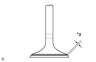 |
Apply a light coat of Prussian blue to the valve face.
| *a | Width |
Lightly press the valve face against the valve seat.
Check the valve face and valve seat.
Intake Side:
Check that the valve seat contacts the middle of the valve face with the width between 1.0 and 1.4 mm (0.0394 and 0.0551 in.).
If not, correct the valve seat.
Exhaust Side:
Check that the valve seat contacts the middle of the valve face with the width between 1.0 and 1.4 mm (0.0394 and 0.0551 in.).
If not, correct the valve seat.
Check that the contact surfaces of the valve seat and valve face are even around the entire valve seat.
If not, correct the valve seat.
| 4. INSPECT CAMSHAFT THRUST CLEARANCE |
Install the camshafts (Click here).
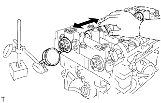 |
Using a dial indicator, measure the thrust clearance while moving the camshaft back and forth.
| 5. INSPECT CAMSHAFT OIL CLEARANCE |
Clean the bearing caps and camshaft journals.
Place the camshafts on the camshaft housing.
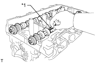 |
Lay a strip of Plastigage across each of the camshaft journals.
| *1 | Plastigage |
Install the bearing caps (Click here).
Remove the bearing caps (Click here).
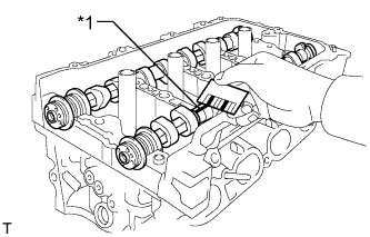 |
Measure the Plastigage at its widest point.
| *1 | Plastigage |
| Item | Specified Condition |
| Camshaft No. 1 Journal | 0.030 to 0.063 mm (0.00118 to 0.00248 in.) |
| Camshaft Other Journals | 0.035 to 0.072 mm (0.00138 to 0.00283 in.) |
| Item | Specified Condition |
| Camshaft No. 1 Journal | 0.085 mm (0.00335 in.) |
| Camshaft Other Journals | 0.09 mm (0.00354 in.) |
| 6. INSPECT COMPRESSION SPRING |
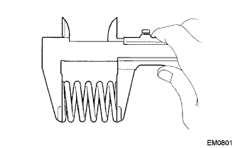 |
Using a vernier caliper, measure the free length of the compression spring.
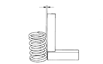 |
Using a steel square, measure the deviation of the compression spring.
| 7. INSPECT INTAKE VALVE |
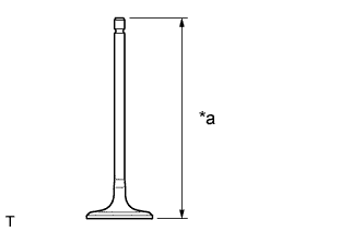 |
Using a vernier caliper, measure the overall length of the valve.
| *a | Overall Length |
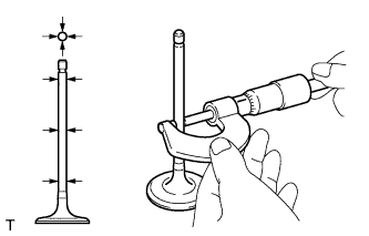 |
Using a micrometer, measure the diameter of the valve stem.
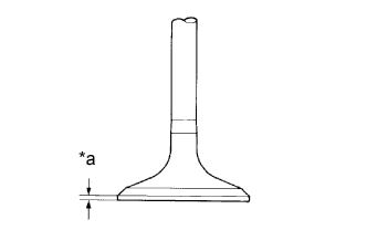 |
Using a vernier caliper, measure the valve head margin thickness.
| *a | Margin Thickness |
| 8. INSPECT EXHAUST VALVE |
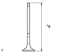 |
Using a vernier caliper, measure the overall length of the valve.
| *a | Overall Length |
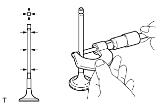 |
Using a micrometer, measure the diameter of the valve stem.
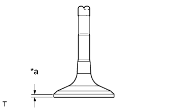 |
Using a vernier caliper, measure the valve head margin thickness.
| *a | Margin Thickness |
| 9. INSPECT VALVE GUIDE BUSH OIL CLEARANCE |
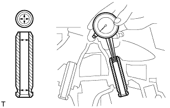 |
Using a caliper gauge, measure the inside diameter of the guide bush.
Subtract the valve stem diameter measurement from the guide bush inside diameter measurement.
| Item | Specified Condition |
| Intake | 0.025 to 0.060 mm (0.000984 to 0.00236 in.) |
| Exhaust | 0.030 to 0.065 mm (0.00118 to 0.00256 in.) |
| Item | Specified Condition |
| Intake | 0.080 mm (0.00315 in.) |
| Exhaust | 0.085 mm (0.00335 in.) |
