ENGINE UNIT > DISASSEMBLY |
| 1. REMOVE OIL FILLER CAP SUB-ASSEMBLY |
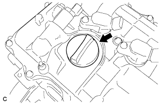 |
Remove the oil filler cap.
| 2. REMOVE OIL FILLER CAP GASKET |
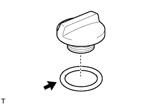 |
Remove the oil filler cap gasket.
| 3. REMOVE ENGINE COVER JOINT BOLT |
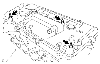 |
Remove the 3 engine cover joint bolts.
| 4. REMOVE WIRING HARNESS CLAMP BRACKET |
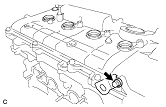 |
Remove the bolt and wiring harness clamp bracket.
| 5. REMOVE SPARK PLUG |
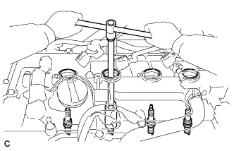 |
Using a 14 mm spark plug wrench, remove the 4 spark plugs.
| 6. REMOVE CAMSHAFT POSITION SENSOR |
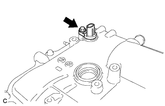 |
Remove the bolt and camshaft position sensor.
| 7. REMOVE CAMSHAFT TIMING OIL CONTROL VALVE ASSEMBLY |
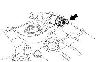 |
Remove the bolt and camshaft timing oil control valve.
Remove the O-ring from the camshaft timing oil control valve.
| 8. REMOVE CRANKSHAFT POSITION SENSOR |
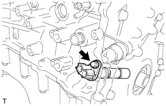 |
Remove the bolt and crankshaft position sensor.
| 9. REMOVE ENGINE OIL PRESSURE SWITCH ASSEMBLY |
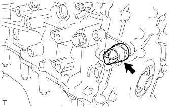 |
Using a 24 mm deep socket wrench, remove the engine oil pressure switch assembly.
| 10. REMOVE KNOCK SENSOR |
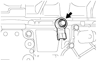 |
Remove the bolt and knock sensor.
| 11. REMOVE ENGINE COOLANT TEMPERATURE SENSOR |
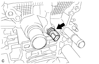 |
Remove the engine coolant temperature sensor and gasket.
| 12. REMOVE CYLINDER HEAD COVER SUB-ASSEMBLY |
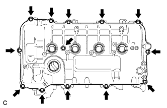 |
Remove the 13 bolts, seal washer and cylinder head cover.
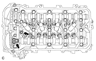 |
Remove the 2 gaskets from the camshaft bearing cap.
| 13. REMOVE CYLINDER HEAD COVER GASKET |
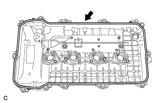 |
Remove the cylinder head cover gasket.
| 14. REMOVE SPARK PLUG TUBE GASKET |
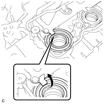 |
Pry up the 4 claws of the ventilation baffle plate.
Remove the 4 gaskets from the cylinder head cover.
| 15. REMOVE OIL FILTER CAP ASSEMBLY |
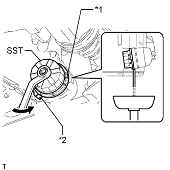 |
Using SST, loosen the oil filter cap 4 revolutions, align the cap ribs vertically, and drain the remaining engine oil in the oil filter cap.
| *1 | Cap Rib |
| *2 | Oil Filter Bracket Clip |
Remove the oil filter cap assembly.
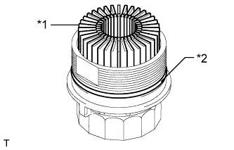 |
Remove the oil filter element and O-ring from the oil filter cap.
| *1 | Oil Filter Element |
| *2 | O-ring |
| 16. REMOVE INLET WATER SUB-ASSEMBLY |
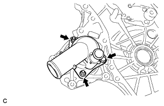 |
Remove the bolt, 2 nuts, inlet water sub-assembly and gasket.
| 17. REMOVE INLET WATER SUB-ASSEMBLY STUD BOLT |
| 18. SET NO. 1 CYLINDER TO TDC/COMPRESSION |
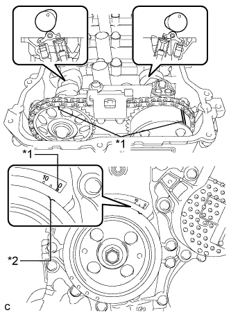 |
Turn the crankshaft pulley until its notch and timing mark "0" of the timing chain cover are aligned.
| *1 | Timing Mark |
| *2 | Timing Notch |
Check that the timing marks on both the camshaft timing sprocket and the camshaft timing gear are facing upward as shown in the illustration.
If not, turn the crankshaft 1 complete revolution (360°) and align the marks as above.
| 19. REMOVE CRANKSHAFT PULLEY |
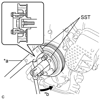 |
Using SST, hold the pulley in place and loosen the pulley bolt.
| *a | Hold |
| *b | Turn |
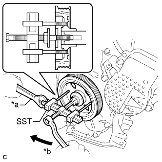 |
Using SST, remove the crankshaft pulley and pulley bolt.
| *a | Hold |
| *b | Turn |
| 20. REMOVE NO. 1 CHAIN TENSIONER ASSEMBLY |
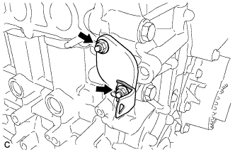 |
Remove the 2 nuts, bracket, chain tensioner and gasket.
| 21. REMOVE TIMING CHAIN COVER SUB-ASSEMBLY |
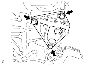 |
Remove the 3 bolts and engine mounting bracket RH.
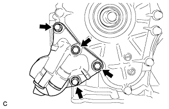 |
Remove the 4 bolts and oil filter bracket.
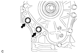 |
Remove the 2 O-rings.
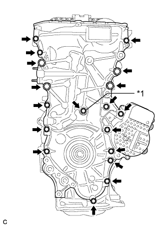 |
Remove the 18 bolts and seal washer.
| *1 | Seal Washer |
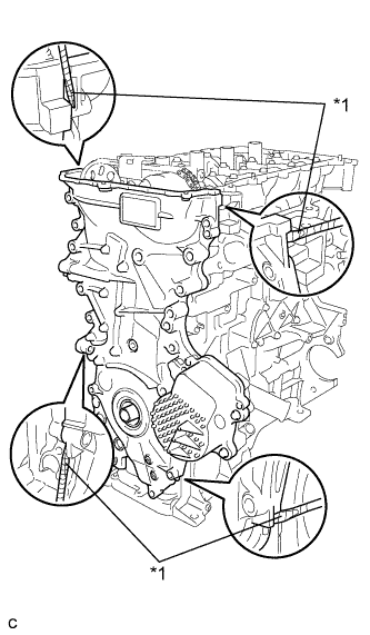 |
Remove the timing chain cover by prying between the timing chain cover and cylinder head or cylinder block with a screwdriver.
| *1 | Protective Tape |
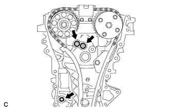 |
Remove the 3 O-rings.
| 22. REMOVE TIMING CHAIN COVER OIL SEAL |
Place the timing chain cover on wooden blocks.
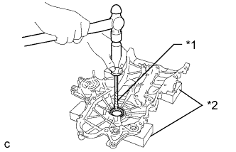 |
Using a screwdriver and hammer, knock out the oil seal.
| *1 | Protective Tape |
| *2 | Wooden Block |
| 23. REMOVE CHAIN TENSIONER SLIPPER |
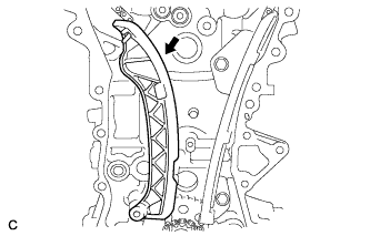 |
Remove the chain tensioner slipper from the cylinder block.
| 24. REMOVE NO. 1 CHAIN VIBRATION DAMPER |
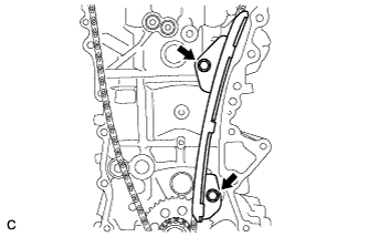 |
Remove the 2 bolts and chain vibration damper.
| 25. REMOVE NO. 2 CHAIN VIBRATION DAMPER |
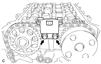 |
Remove the 2 bolts and No. 2 chain vibration damper.
| 26. REMOVE CHAIN SUB-ASSEMBLY |
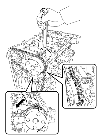 |
Hold the hexagonal portion of the camshaft with a wrench and turn the camshaft timing gear counterclockwise to loosen the chain between the camshaft timing gears.
With the chain loosened, release the chain from the camshaft timing gear and place it on the camshaft timing gear.
Turn the camshaft clockwise to return it to the original position and remove the chain.
| 27. REMOVE CRANKSHAFT TIMING SPROCKET |
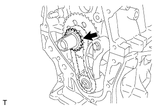 |
Remove the crankshaft timing sprocket.
| 28. REMOVE NO. 2 CHAIN SUB-ASSEMBLY |
Temporarily tighten the crankshaft pulley and crankshaft pulley bolt.
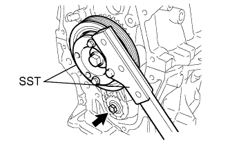 |
Using SST, remove the oil pump drive shaft sprocket nut while holding the crankshaft pulley.
Remove SST, the crankshaft pulley and crankshaft pulley bolt.
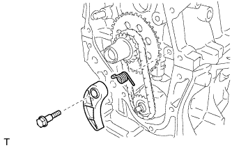 |
Remove the bolt, chain tensioner plate and chain damper spring.
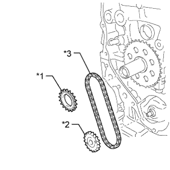 |
Remove the oil pump drive gear, oil pump drive shaft gear and No. 2 chain sub-assembly.
| *1 | Oil Pump Drive Gear |
| *2 | Oil Pump Drive Shaft Gear |
| *3 | No. 2 Chain Sub-assembly |
| 29. REMOVE NO. 1 CRANKSHAFT POSITION SENSOR PLATE |
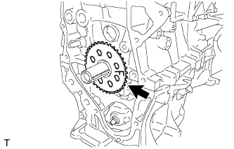 |
Remove the crankshaft position sensor plate.
| 30. REMOVE CRANKSHAFT TIMING GEAR KEY |
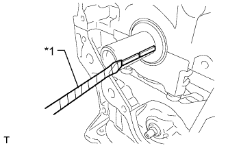 |
Using a screwdriver, remove the 2 crankshaft timing gear keys.
| *1 | Protective Tape |
| 31. INSPECT CAMSHAFT TIMING GEAR ASSEMBLY |
Inspect the lock of the camshaft timing gear.
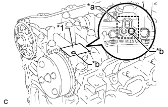 |
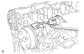
After cleaning and degreasing the VVT oil hole on the intake side of the No. 1 camshaft bearing cap, completely seal the oil hole with adhesive tape or equivalent as shown in the illustration to prevent air from leaking.
| *1 | Adhesive Tape |
| *a | Adhesive Tape Sealing Area |
| *b | Prick a Hole |
Prick a hole in the tape covering the oil hole as shown in the illustration. (Procedure A)
 |
Apply approximately 150 kPa (1.5 kgf/cm2, 22 psi) of air pressure to the hole pricked in procedure A to release the lock pin.
Forcibly turn the camshaft timing gear in the advance direction (counterclockwise).
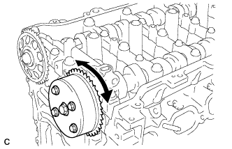 |
Turn the camshaft timing gear within its movable range (26.5 to 28.5°) 2 or 3 times without turning it to the most retarded position. Make sure that the camshaft timing gear turns smoothly.
Remove the adhesive tape from the No. 1 camshaft bearing cap.
| 32. REMOVE CAMSHAFT TIMING GEAR ASSEMBLY |
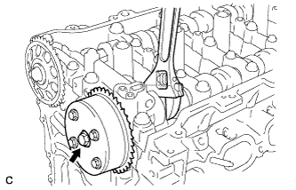 |
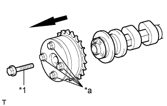
Remove the flange bolt while holding the hexagonal portion of the camshaft with a wrench, and then remove the camshaft timing gear.
| *1 | Flange Bolt |
| *a | Do not remove |
 |
| 33. REMOVE CAMSHAFT TIMING SPROCKET |
|
Remove the flange bolt while holding the hexagonal portion of the camshaft with a wrench, and then remove the camshaft timing gear.
| *1 | Flange Bolt |
| *a | Do not remove |
|
| 34. REMOVE CAMSHAFT BEARING CAP |
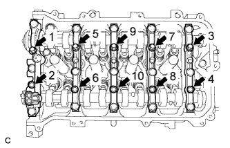 |
Uniformly loosen and remove the 10 bearing cap bolts in the sequence shown in the illustration.
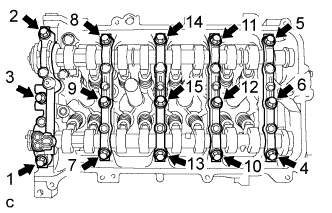 |
Uniformly loosen and remove the 15 bearing cap bolts in the sequence shown in the illustration.
Remove the 5 bearing caps.
| 35. REMOVE CAMSHAFT |
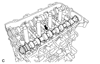 |
Remove the camshaft.
| 36. REMOVE NO. 2 CAMSHAFT |
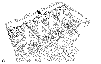 |
Remove the No. 2 camshaft.
| 37. REMOVE CAMSHAFT HOUSING STRAIGHT PIN |
| 38. REMOVE NO. 1 VALVE ROCKER ARM SUB-ASSEMBLY |
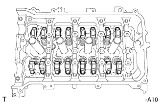 |
Remove the 16 valve rocker arms.
| 39. REMOVE VALVE LASH ADJUSTER ASSEMBLY |
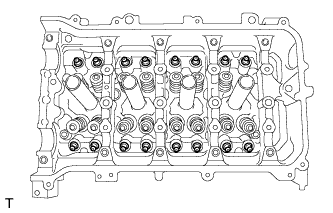 |
Remove the 16 valve lash adjusters from the cylinder head.
| 40. REMOVE VALVE STEM CAP |
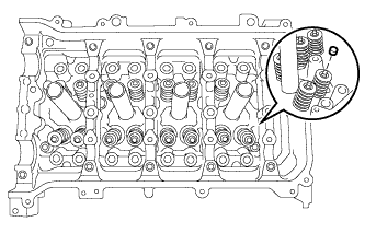 |
Remove the 16 valve stem caps.
| 41. REMOVE OIL CONTROL VALVE FILTER |
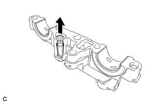 |
Remove the oil control valve filter from the No. 1 camshaft bearing cap.
| 42. REMOVE NO. 1 CAMSHAFT BEARING |
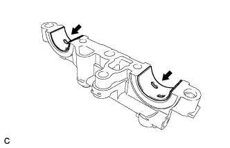 |
Remove the 2 camshaft bearings.
| 43. REMOVE NO. 2 CAMSHAFT BEARING |
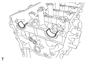 |
Remove the 2 camshaft bearings.
| 44. REMOVE CAMSHAFT HOUSING SUB-ASSEMBLY |
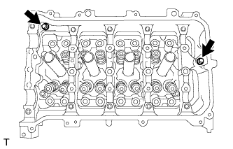 |
Remove the 2 bolts.
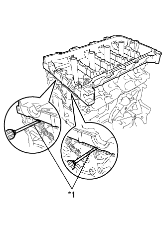 |
Remove the camshaft housing by prying between the cylinder head and camshaft housing with a screwdriver.
| *1 | Protective Tape |
| 45. REMOVE CYLINDER HEAD SUB-ASSEMBLY |
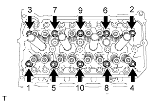 |
Using a 10 mm bi-hexagon wrench, uniformly loosen and remove the 10 cylinder head bolts and 10 plate washers in several steps in the sequence shown in the illustration.
Using a screwdriver with its tip wrapped with tape, pry between the cylinder head and cylinder block, and remove the cylinder head.
| 46. REMOVE CYLINDER HEAD GASKET |
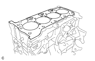 |
Remove the cylinder head gasket.
| 47. REMOVE VENTILATION VALVE SUB-ASSEMBLY |
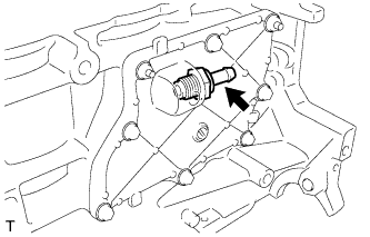 |
Remove the ventilation valve sub-assembly.
| 48. REMOVE OIL PAN DRAIN PLUG |
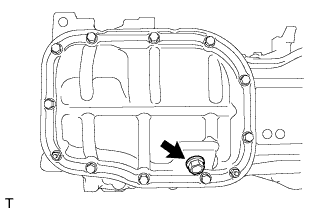 |
Remove the drain plug and gasket.
| 49. REMOVE NO. 2 OIL PAN SUB-ASSEMBLY |
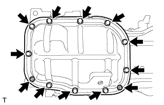 |
Remove the 10 bolts and 2 nuts.
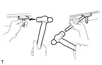 |
Insert the blade of an oil pan seal cutter between the crankcase and oil pan. Cut through the sealer and remove the oil pan.
| 50. REMOVE OIL PUMP ASSEMBLY |
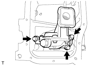 |
Remove the 3 bolts and oil pump.
| 51. REMOVE STIFFENING CRANKCASE ASSEMBLY |
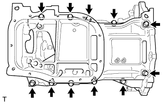 |
Uniformly loosen and remove the 11 bolts.
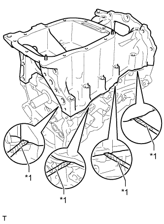 |
Using a screwdriver, remove the stiffening crankcase by prying between the stiffening crankcase and cylinder block.
| *1 | Protective Tape |
| 52. REMOVE NO. 1 TAPER SCREW PLUG |
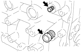 |
Remove the 2 No. 1 taper screw plugs.
| 53. REMOVE STIFFENING CRANKCASE STUD BOLT |
| 54. REMOVE STIFFENING CRANKCASE RING PIN |
| 55. REMOVE ENGINE REAR OIL SEAL |
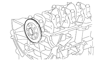 |
Remove the engine rear oil seal from the cylinder block.
