CYLINDER BLOCK > DISASSEMBLY |
| 1. REMOVE NO. 1 VENTILATION CASE |
Type A:
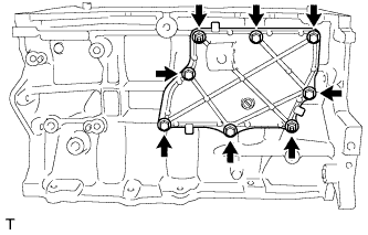 |
Remove the 6 bolts and 2 nuts.
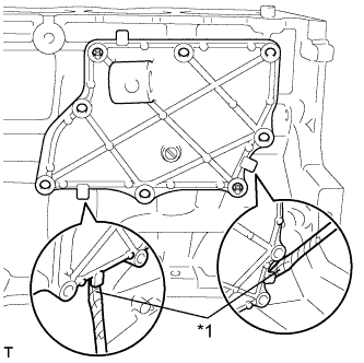 |
Remove the ventilation case by prying between the ventilation case and cylinder block with a screwdriver as shown in the illustration.
| *1 | Protective Tape |
Using an E6 "TORX" socket, remove the 2 stud bolts.
Type B:
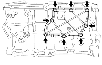 |
Remove the 8 bolts.
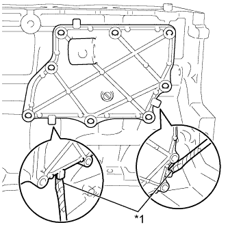 |
Remove the ventilation case by prying between the ventilation case and cylinder block with a screwdriver as shown in the illustration.
| *1 | Protective Tape |
| 2. INSPECT CONNECTING ROD THRUST CLEARANCE |
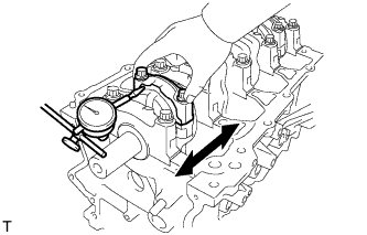 |
Using a dial indicator, measure the thrust clearance while moving the connecting rod cap back and forth.
| 3. INSPECT CONNECTING ROD OIL CLEARANCE |
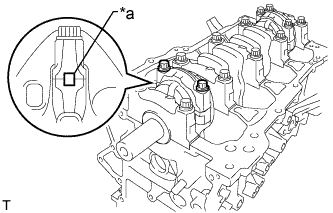 |
Check that the matchmarks on the connecting rod and cap are aligned to ensure correct reassembly.
| *a | Matchmark |
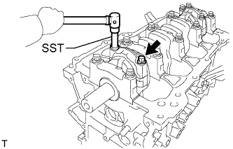 |
Using SST, uniformly loosen the 2 bolts.
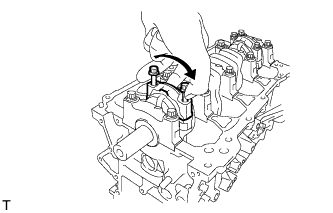 |
Using the 2 removed connecting rod cap bolts, remove the connecting rod cap and lower bearing by wiggling the connecting rod cap right and left.
Clean the crank pin and bearing.
Check the crank pin and bearing for pitting and scratches.
If the crank pin or bearing is damaged, replace the bearings. If necessary, replace the crankshaft.
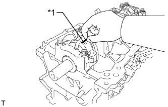 |
Lay a strip of Plastigage on the crank pin.
| *1 | Plastigage |
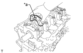 |
Check that the front mark of the connecting rod cap is facing forward and install the connecting rod cap.
| *a | Front Mark |
Apply a light coat of engine oil to the threads and under the heads of the connecting rod cap bolts.
Install the connecting rod cap bolts.
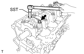 |
Step 1:
Using SST, install and alternately tighten the bolts of the connecting rod cap in several steps.
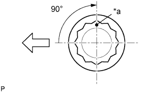 |
Step 2:
| *a | Paint Mark |
 | Engine Front |
Mark the front of the connecting rod cap bolts with paint.
Tighten the cap bolts 90° as shown in the illustration.
Remove the 2 bolts and connecting rod cap.
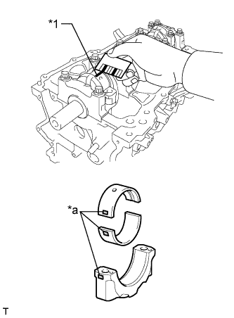 |
Measure the Plastigage at its widest point.
| *1 | Plastigage |
| *a | Mark 1, 2 or 3 |
| Mark | Specified Condition |
| Mark 1 | 47.000 to 47.008 mm (1.85039 to 1.85071 in.) |
| Mark 2 | 47.009 to 47.016 mm (1.85074 to 1.85102 in.) |
| Mark 3 | 47.017 to 47.024 mm (1.85106 to 1.85133 in.) |
| Mark | Specified Condition |
| Mark 1 | 1.489 to 1.493 mm (0.05862 to 0.05878 in.) |
| Mark 2 | 1.494 to 1.497 mm (0.05882 to 0.05894 in.) |
| Mark 3 | 1.498 to 1.501 mm (0.05898 to 0.05909 in.) |
Perform the inspection above for each cylinder.
| 4. REMOVE PISTON SUB-ASSEMBLY WITH CONNECTING ROD |
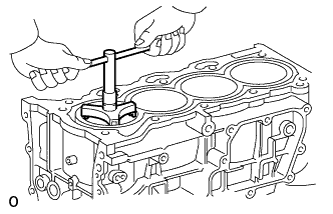 |
Using a ridge reamer, remove all the carbon from the top of the cylinder.
Push the piston, connecting rod and upper bearing through the top of the cylinder block.
| 5. REMOVE CONNECTING ROD BEARING |
Remove the connecting rod bearings.
| 6. REMOVE PISTON RING SET |
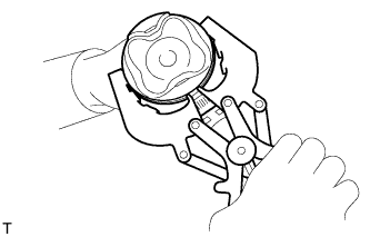 |
Using a piston ring expander, remove the 2 compression rings.
Remove the oil ring and oil ring expander by hand.
| 7. REMOVE PISTON |
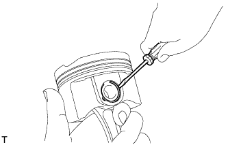 |
Using a screwdriver, pry out the 2 snap rings.
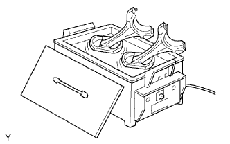 |
Gradually heat each piston to approximately 80 to 90°C (176 to 194°F).
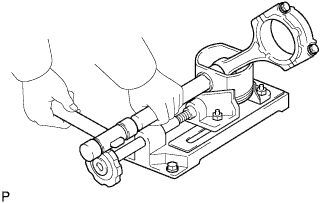 |
Using a plastic-faced hammer and brass bar, lightly tap out the piston pin and remove the connecting rod.
| 8. INSPECT CRANKSHAFT THRUST CLEARANCE |
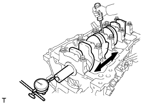 |
Using a dial indicator, measure the thrust clearance while prying the crankshaft back and forth with a screwdriver.
| 9. REMOVE CRANKSHAFT |
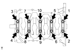 |
Uniformly loosen and remove the 10 crankshaft bearing cap bolts in the sequence shown in the illustration.
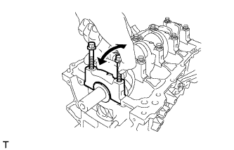 |
Using the 2 removed crankshaft bearing cap bolts, remove the 5 crankshaft bearing caps and 5 lower bearings.
Lift out the crankshaft.
Check each crankshaft journal and bearing for pitting and scratches.
If the journal or bearing is damaged, replace the bearings. If necessary, replace the crankshaft.
| 10. REMOVE UPPER CRANKSHAFT THRUST WASHER |
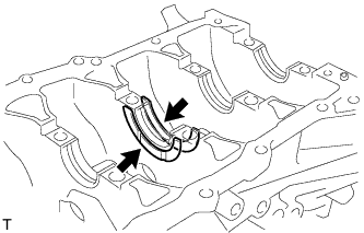 |
Remove the 2 upper crankshaft thrust washers from the cylinder block.
| 11. REMOVE CRANKSHAFT BEARING |
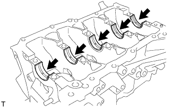 |
Remove the 5 upper crankshaft bearings from the cylinder block.
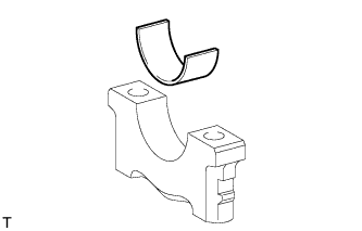 |
Remove the 5 lower crankshaft bearings from the 5 crankshaft bearing caps.
| 12. REMOVE NO. 1 OIL NOZZLE SUB-ASSEMBLY |
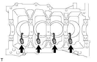 |
Using a 5 mm socket hexagon wrench, remove the 4 bolts and 4 oil nozzles.
| 13. CLEAN CYLINDER BLOCK |
| 14. REMOVE STUD BOLT |
