ENGINE UNIT > REASSEMBLY |
| 1. INSTALL STIFFENING CRANKCASE RING PIN |
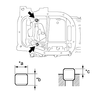 |
| *a | Width |
| *b | Height |
| *c | Protrusion Height |
Using a plastic-faced hammer, tap in 2 new ring pins until they stop.
| Item | Protrusion Height | Height | Width |
| Ring pin | 3.0 mm (0.118 in.) | 8 mm (0.315 in.) | 11 mm (0.433 in.) |
| 2. INSTALL STIFFENING CRANKCASE STUD BOLT |
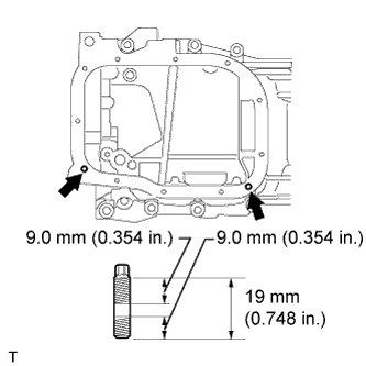 |
Using an E6 "TORX" socket wrench, install the stud bolts as shown in the illustration.
| 3. INSTALL STIFFENING CRANKCASE ASSEMBLY |
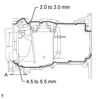 |
Apply seal packing in a continuous line as shown in the illustration.
| Area | Specified Condition |
| Continuous Line | 2.0 to 3.0 mm (0.0787 to 0.118 in.) |
| A | 4.5 to 5.5 mm (0.177 to 0.217 in.) |
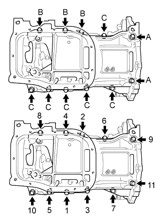 |
Install the stiffening crankcase with the 11 bolts in the sequence shown in the illustration.
| Item | Specified Condition |
| Bolt A | 138 mm (5.43 in.) |
| Bolt B | 35 mm (1.38 in.) |
| Bolt C | 70 mm (2.76 in.) |
Recheck the torque for bolts 1 and 2.
Wipe off any excess seal packing with a clean piece of cloth.
| 4. INSTALL OIL PUMP ASSEMBLY |
Install the oil pump with the 3 bolts.
| 5. INSTALL NO. 2 OIL PAN SUB-ASSEMBLY |
Remove any old packing material and be careful not to drop any oil on the contact surfaces of the cylinder block and oil pan.
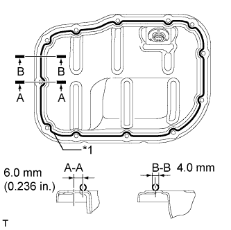 |
Apply a continuous bead of seal packing (diameter 4.0 mm (0.157 in.)) as shown in the illustration.
| *1 | Seal Packing |
Install the No. 2 oil pan with the 10 bolts and 2 nuts.
| 6. INSTALL OIL PAN DRAIN PLUG |
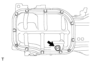 |
Install a new gasket and the drain plug.
| 7. INSTALL ENGINE REAR OIL SEAL |
Apply MP grease to the lip of a new oil seal.
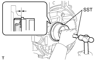 |
Using SST and a hammer, tap in the oil seal until its surface is flush with the rear oil seal retainer edge.
| 8. INSTALL NO. 1 TAPER SCREW PLUG |
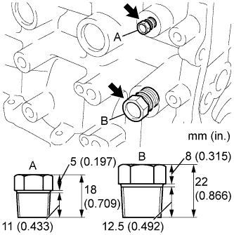 |
Apply adhesive to 2 or 3 threads of the No. 1 taper screw plug, and install the No. 1 taper screw plug (A).
Apply adhesive to 2 or 3 threads of the No. 1 taper screw plug, and install the No. 1 taper screw plug (B).
| 9. INSTALL VENTILATION VALVE SUB-ASSEMBLY |
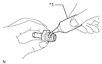 |
Apply adhesive to the threads of the ventilation valve sub-assembly.
| *1 | Adhesive |
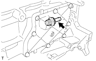 |
Install the ventilation valve sub-assembly.
| 10. INSTALL CYLINDER HEAD GASKET |
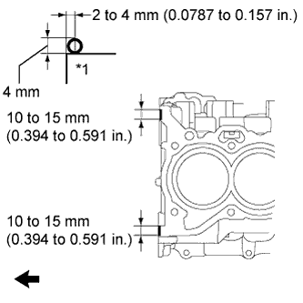 |
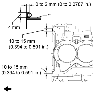
Apply seal packing (diameter 4.0 mm (0.157 in.)) to the cylinder block as shown in the illustration.
| *1 | Cylinder Block |
 | Engine Front |
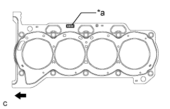 |
Place a new cylinder head gasket on the cylinder block with the Lot No. stamp facing upward.
| *a | Lot No. |
| Engine Front |
 |
Apply seal packing (diameter 4.0 mm (0.157 in.)) to the new cylinder head gasket as shown in the illustration.
| *1 | Cylinder Head Gasket |
| Engine Front |
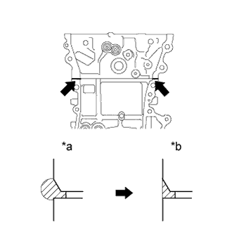 |
After tightening the cylinder head bolts, wipe off any seal packing material that seeped out from the contact surfaces between the cylinder head and cylinder block.
| *a | Before wiping off |
| *b | After wiping off |
| 11. INSTALL CYLINDER HEAD SUB-ASSEMBLY |
Place the cylinder head on the cylinder block.
Install the plate washers to the cylinder head bolts.
Apply a light coat of engine oil to the threads and under the heads of the cylinder head bolts.
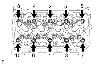 |
Step 1:
Using a 10 mm bi-hexagon wrench, install and uniformly tighten the 10 cylinder head bolts in several steps, in the sequence shown in the illustration.
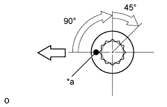 |
Step 2:
| *a | Paint Mark |
 | Engine Front |
Mark each cylinder head bolt head with paint as shown in the illustration.
Tighten the cylinder head bolts 90° in the sequence shown in step 1.
Step 3:
Tighten the cylinder head bolts another 45° in the sequence shown in step 1.
Check that the paint mark is now at a 135° angle to the front.
| 12. INSTALL VALVE STEM CAP |
Apply a light coat of engine oil to the valve stem ends.
Install the 16 valve stem caps to the cylinder head.
| 13. INSTALL VALVE LASH ADJUSTER ASSEMBLY |
Inspect each valve lash adjuster before installing it (Click here).
Install the 16 valve lash adjusters to the cylinder head.
| 14. INSTALL NO. 1 VALVE ROCKER ARM SUB-ASSEMBLY |
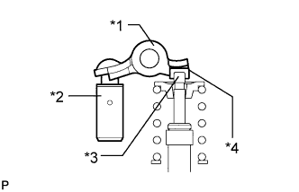 |
Apply engine oil to the valve lash adjuster tips and valve stem cap ends.
| *1 | Valve Rocker Arm |
| *2 | Valve Lash Adjuster |
| *3 | Valve Stem |
| *4 | Valve Stem Cap |
Make sure that the No. 1 valve rocker arms are installed as shown in the illustration.
| 15. INSTALL CAMSHAFT HOUSING STRAIGHT PIN |
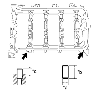 |
| *a | Width |
| *b | Height |
| *c | Protrusion Height |
Using a plastic-faced hammer, tap in a new straight pin to the specified protrusion height.
| Item | Protrusion Height | Height | Width |
| Straight pin | 6.5 to 7.5 mm (0.256 to 0.295 in.) | 14 mm (0.551 in.) | 6.0 mm (0.236 in.) |
| 16. INSTALL NO. 1 CAMSHAFT BEARING |
Clean both surfaces of the bearings.
Install the 2 No. 1 camshaft bearings.
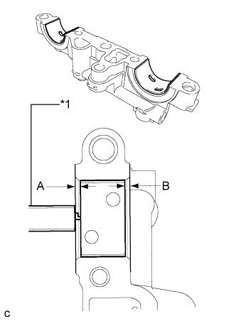 |
Using a vernier caliper, measure the distance between the bearing cap edge and the camshaft bearing edge.
| *1 | Vernier Caliper |
| 17. INSTALL OIL CONTROL VALVE FILTER |
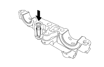 |
Check that no foreign matter is on the mesh part of the oil control valve filter.
Install the oil control valve filter.
| 18. INSTALL NO. 2 CAMSHAFT BEARING |
Clean both surfaces of the bearings.
Install the 2 No. 2 camshaft bearings.
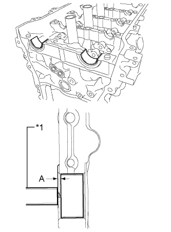 |
Using a vernier caliper, measure the distance between the bearing cap edge and the camshaft bearing edge.
| *1 | Vernier Caliper |
| 19. INSTALL NO. 2 CAMSHAFT |
Clean the camshaft journals.
Apply a light coat of engine oil to the camshaft journals, camshaft housings and bearing caps.
Install the No. 2 camshaft to the camshaft housing.
| 20. INSTALL CAMSHAFT |
Clean the camshaft journals.
Apply a light coat of engine oil to the camshaft journals, camshaft housings and bearing caps.
Install the camshaft to the camshaft housing.
| 21. INSTALL CAMSHAFT BEARING CAP |
Apply engine oil to the camshaft journals, camshaft housings and bearing caps.
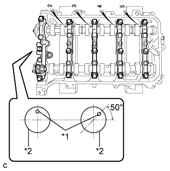 |
Make sure of the marks and numbers on the camshaft bearing caps and place them in each proper position and direction.
| *1 | Knock Pin |
| *2 | Camshaft |
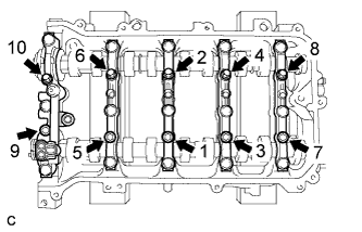 |
Tighten the 10 bolts in the order shown in the illustration.
| 22. INSTALL CAMSHAFT HOUSING SUB-ASSEMBLY |
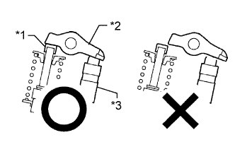 |
Check that the valve rocker arms are installed as shown in the illustration.
| *1 | Valve Stem Cap |
| *2 | Valve Rocker Arm |
| *3 | Valve Lash Adjuster |
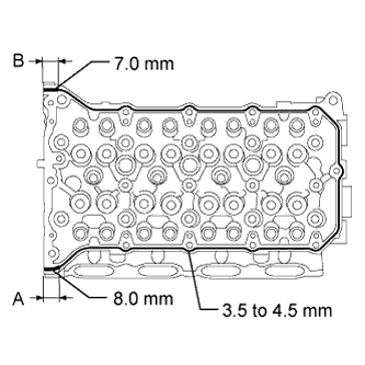 |
Apply seal packing in a continuous line as shown in the illustration.
| Area | Specified Condition |
| Continuous line | 3.5 to 4.5 mm (0.138 to 0.177 in.) |
| A | 8.0 mm (0.315 in.) |
| B | 7.0 mm (0.276 in.) |
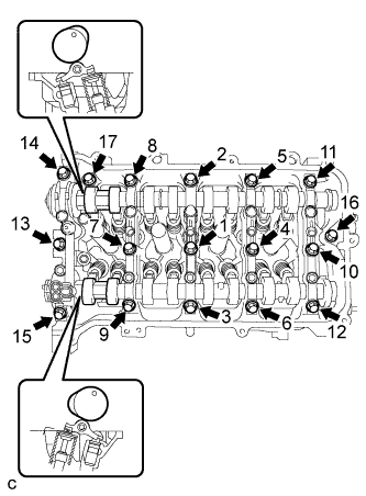 |
Set the camshaft and No. 2 camshaft as shown in the illustration.
Install the camshaft housing with the 17 bolts and tighten them in the order shown in the illustration.
| 23. INSTALL CAMSHAFT TIMING SPROCKET |
Tighten the flange bolt with the camshaft timing sprocket secured in place.
| 24. INSTALL CAMSHAFT TIMING GEAR ASSEMBLY |
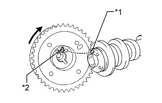 |
Put the camshaft timing gear and camshaft together with the straight pin and key groove misaligned as shown in the illustration.
| *1 | Straight Pin |
| *2 | Key Groove |
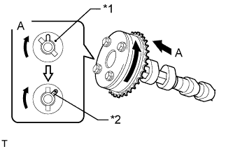 |
Turn the camshaft timing gear as shown in the illustration while pushing it gently against the camshaft. Push further at the position where the pin fits into the groove.
| *1 | Straight Pin |
| *2 | Key Groove |
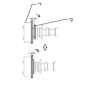 |
Check that there is no clearance between the camshaft timing gear and camshaft flange.
| *1 | Camshaft Timing Gear |
| *2 | Flange |
| *a | Clearance |
| *b | No Clearance |
Tighten the flange bolt with the camshaft timing gear secured in place.
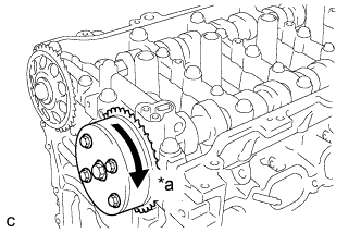 |
Check that the camshaft timing gear can move in the retard direction (clockwise) and lock it in the most retarded position.
| *a | Lock |
| 25. INSTALL CRANKSHAFT TIMING GEAR KEY |
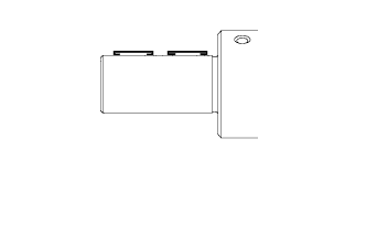 |
Using a plastic-faced hammer, tap in the 2 crankshaft timing gear keys.
| 26. INSTALL NO. 1 CRANKSHAFT POSITION SENSOR PLATE |
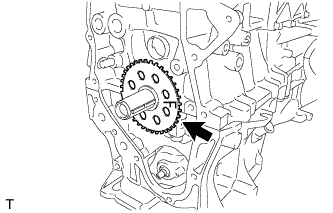 |
Install the crankshaft position sensor plate with the "F" mark facing forward.
| 27. INSTALL NO. 2 CHAIN SUB-ASSEMBLY |
Temporarily install the crankshaft pulley bolt.
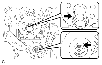 |
Turn the crankshaft counterclockwise to position the timing gear key at the 9 o'clock position.
Turn the drive shaft so that the cutout faces the 12 o'clock position.
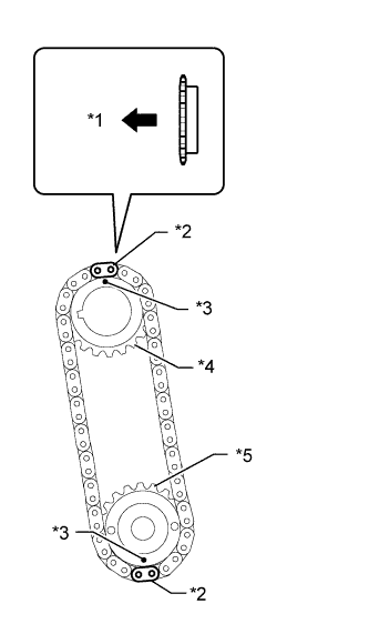 |
Align the yellow mark links with the timing marks of each gear as shown in the illustration.
| *1 | Front |
| *2 | Mark Plate (Yellow) |
| *3 | Timing Mark |
| *4 | Oil Pump Drive Gear |
| *5 | Oil Pump Drive Shaft Gear |
Install the sprockets onto the crankshaft and oil pump shaft with the chain on the gears.
Temporarily tighten the oil pump drive shaft gear with the nut.
Insert the damper spring into the adjusting hole, and then install the chain tensioner plate with the bolt.
Temporarily tighten the crankshaft pulley with the bolt.
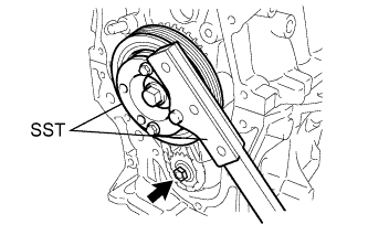 |
Using SST, install the oil pump drive shaft gear nut while holding the crankshaft pulley.
Remove the crankshaft pulley and bolt.
| 28. INSTALL CRANKSHAFT TIMING SPROCKET |
Install the crankshaft timing sprocket.
| 29. INSTALL NO. 1 CHAIN VIBRATION DAMPER |
Install the chain vibration damper with the 2 bolts.
| 30. SET NO. 1 CYLINDER TO TDC/COMPRESSION |
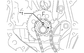 |
Temporarily install the crankshaft pulley bolt.
| *1 | Timing Gear Key |
Turn the crankshaft to position the timing gear key to the top.
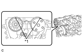 |
Check that the timing marks on the camshaft timing gear and camshaft timing sprocket are aligned as shown in the illustration.
| *1 | Timing Mark |
Remove the crankshaft pulley bolt.
| 31. INSTALL CHAIN SUB-ASSEMBLY |
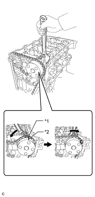 |
Align the mark plate (orange) with the timing mark as shown in the illustration and install the chain.
| *1 | Mark Plate (Orange) |
| *2 | Timing Mark |
Hold the hexagonal portion of the camshaft with a wrench and turn the camshaft timing gear counterclockwise to align the mark plate (orange) and timing mark, and then install the chain.
Hold the hexagonal portion of the camshaft with a wrench and turn the camshaft timing gear clockwise.
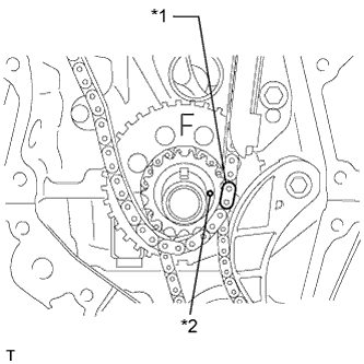 |
Align the mark plate (yellow) and timing mark and install the chain to the crankshaft timing gear.
| *1 | Mark Plate (Yellow) |
| *2 | Timing Mark |
| 32. CHECK NO. 1 CYLINDER TO TDC/COMPRESSION |
Check each timing mark at TDC/compression.
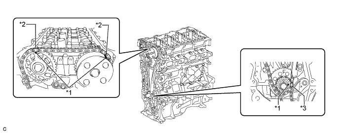
| *1 | Timing Mark | *2 | Mark Plate (Orange) |
| *3 | Mark Plate (Yellow) | - | - |
| 33. INSTALL CHAIN TENSIONER SLIPPER |
Install the chain tensioner slipper to the cylinder block.
| 34. INSTALL NO. 2 CHAIN VIBRATION DAMPER |
Install the No. 2 chain vibration damper with the 2 bolts.
| 35. INSTALL INLET WATER SUB-ASSEMBLY STUD BOLT |
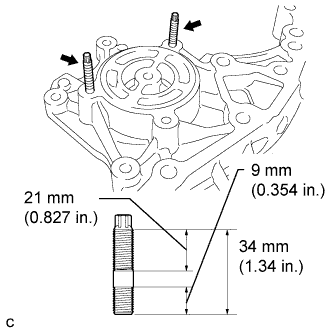 |
Using an E5 "TORX" socket wrench, install the stud bolts as shown in the illustration.
| 36. INSTALL INLET WATER SUB-ASSEMBLY |
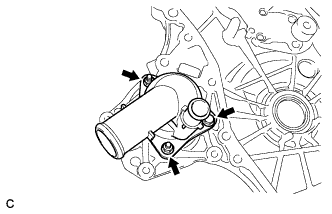 |
Install a new gasket and the inlet water sub-assembly with the bolt and 2 nuts.
| 37. INSTALL TIMING CHAIN COVER SUB-ASSEMBLY |
Remove any old packing (FIPG) material and be careful not to drop any oil on the contact surfaces of the timing chain cover, cylinder head and cylinder block.
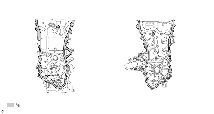
| *a | Clean and degrease | - | - |
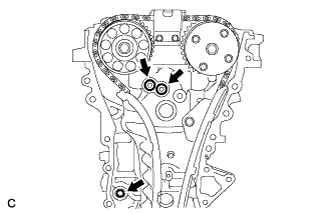 |
Install 3 new O-rings.
Apply seal packing as shown in the illustration.
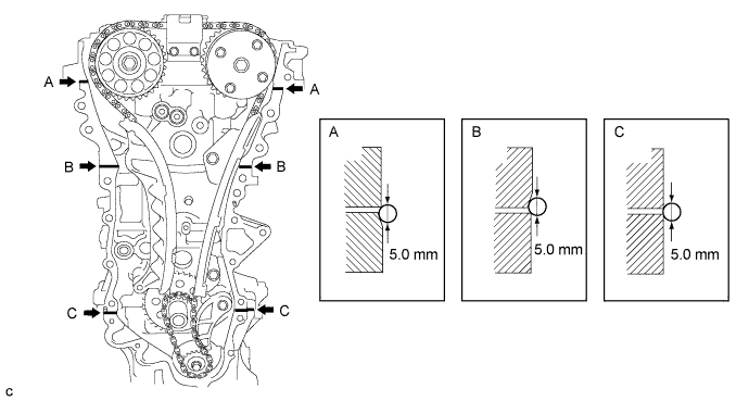
Apply seal packing to the timing chain cover in a line as shown in the following illustration.
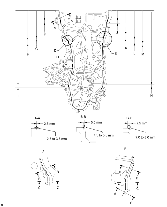
| Item | Seal Packing |
| Dashed line | Toyota Genuine Seal Packing Black, Three Bond 1207B or equivalent |
| Continuous line | |
| Alternate long and short dashed line | Toyota Genuine Seal Packing 1282B, Three Bond 1282B or equivalent |
| Area | Seal Packing Diameter | Distance from Edge of Cover to: | Seal Packing Application Length | Distance from Top of Cover to Top of Seal Packing |
| Dashed line | 2.5 to 3.0 mm (0.0984 to 0.118 in.) | Center of seal packing 2.5 mm (0.0984 in.) | - | - |
| Continuous line | 4.5 to 5.5 mm (0.177 to 0.217 in.) or 7.0 to 8.0 mm (0.276 to 0.315 in.) | - | - | - |
| Alternate long and short dashed line | 4.0 mm (0.157 in.) | Center of seal packing 3.0 mm (0.118 in.) | - | - |
| A - A | 2.5 to 3.5 mm (0.0984 to 0.138 in.) | Center of seal packing 2.5 mm (0.0984 in.) | - | - |
| B - B | 4.5 to 5.5 mm (0.177 to 0.217 in.) | Opposite edge of seal packing 5.0 mm (0.197 in.) | - | - |
| C - C | 7.0 to 8.0 mm (0.276 to 0.315 in.) | Opposite edge of seal packing 7.5 mm (0.295 in.) | - | - |
| F | 4.5 to 5.5 mm (0.177 to 0.217 in.) | - | 15.5 mm (0.610 in.) | 50.4 mm (1.98 in.) |
| G | 4.5 to 5.5 mm (0.177 to 0.217 in.) | - | 10.3 mm (0.406 in.) | 143.1 mm (5.63 in.) |
| H | 7.0 to 8.0 mm (0.276 to 0.315 in.) | - | 19.5 mm (0.768 in.) | 153.4 mm (6.04 in.) |
| I | 4.5 to 5.5 mm (0.177 to 0.217 in.) | - | 16.0 mm (0.630 in.) | 385.8 mm (1.27 ft.) |
| J | 4.5 to 5.5 mm (0.177 to 0.217 in.) | - | 18.6 mm (0.732 in.) | 51.4 mm (2.02 in.) |
| K | 4.5 to 5.5 mm (0.177 to 0.217 in.) | - | 25.3 mm (0.996 in.) | 121.9 mm (4.80 in.) |
| L | 7.0 to 8.0 mm (0.276 to 0.315 in.) | - | 25.8 mm (1.02 in.) | 147.2 mm (5.80 in.) |
| M | 4.5 to 5.5 mm (0.177 to 0.217 in.) | - | 5.1 mm (0.201 in.) | 173.0 mm (6.81 in.) |
| N | 4.5 to 5.5 mm (0.177 to 0.217 in.) | - | 14.6 mm (0.575 in.) | 385.8 mm (1.27 ft.) |
| O | 4.0 mm (0.157 in.) | Center of seal packing 3.0 mm (0.118 in.) | - | - |
Clean the bolt and fitting hole.
Install the timing chain cover.
Temporarily tighten the engine mounting bracket RH with the 3 bolts.
| Item | Length |
| Bolt | 80 mm (3.15 in.) |
Install 2 new O-rings.
Temporarily tighten the oil filter bracket with the 4 bolts.
| Item | Length |
| Bolt | 35 mm (1.38 in.) |
Install the timing chain cover with the 25 bolts and seal washer as shown in the illustration.
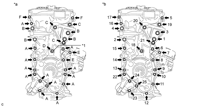
| *1 | Seal Washer | - | - |
| *a | Torque | *b | Bolt Torque Order |
| Item | Length |
| Bolt A, F | 35 mm (1.38 in.) |
| Bolt B | 55 mm (2.16 in.) |
| Bolt C | 80 mm (3.15 in.) |
| Bolt D | 40 mm (1.57 in.) |
| Bolt E | 55 mm (2.16 in.) |
| 38. INSTALL TIMING CHAIN COVER OIL SEAL |
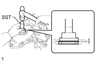 |
Using SST and a hammer, tap in a new oil seal until its surface is flush with the timing chain cover edge.
Apply MP grease to the lip of the oil seal.
| 39. INSTALL CRANKSHAFT PULLEY |
Align the pulley set key with the key groove of the pulley.
Install the crankshaft pulley to the crankshaft.
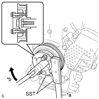 |
Using SST, hold the pulley in place and tighten the bolt.
| *a | Hold |
| *b | Turn |
| 40. INSTALL NO. 1 CHAIN TENSIONER ASSEMBLY |
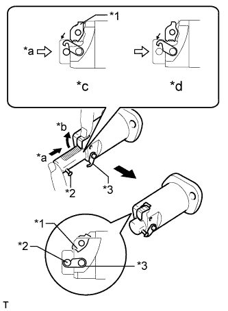 |
Release the cam, and then fully push in the plunger and engage the hook to the pin so that the plunger is in the position shown in the illustration.
| *1 | Cam |
| *2 | Pin |
| *3 | Hook |
| *a | Push |
| *b | Raise |
| *c | CORRECT |
| *d | INCORRECT |
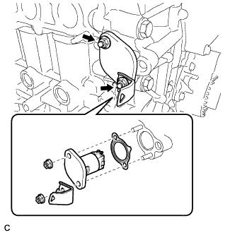 |
Install a new gasket, the bracket and chain tensioner with the 2 nuts.
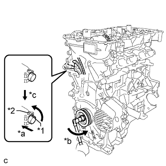 |
Rotate the crankshaft counterclockwise slightly and check that the hook is released.
| *1 | Pin |
| *2 | Hook |
| *a | Push |
| *b | Turn |
| *c | Disconnect |
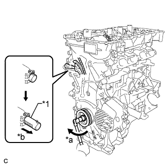 |
Turn the crankshaft clockwise and check that the plunger is extended.
| *1 | Plunger |
| *a | Turn |
| *b | Plunger Extended |
| 41. INSTALL OIL FILTER CAP ASSEMBLY |
Clean the oil filter cap threads and O-ring groove.
Apply a small amount of engine oil to a new O-ring and install it to the oil filter cap.
Set a new oil filter element in the oil filter cap.
Remove any dirt or foreign matter from the installation surface and inside of the engine.
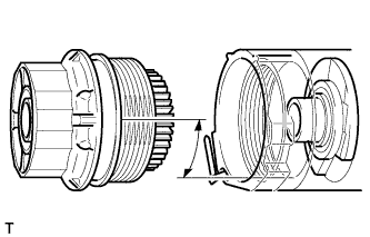 |
Reapply a small amount of engine oil to the O-ring of the oil filter cap assembly. Align the cutout in the oil filter cap threads 90° to the grooves in the oil filter bracket and temporarily tighten the cap.
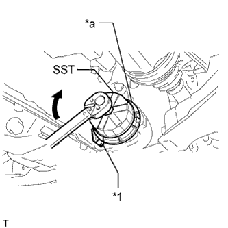 |
Using SST, tighten the oil filter cap assembly.
| *1 | Oil Filter Bracket Clip |
| *a | No Clearance |
| 42. INSTALL SPARK PLUG TUBE GASKET |
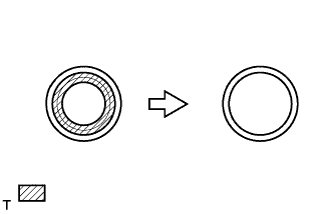 |
Using a cutter knife, cut off the seal part of the removed gasket.
 | Part to Cut Off |
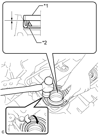 |
Using a hammer and the plug tube gasket which has had the sealing part cut off, uniformly tap in a new plug tube gasket all the way.
| *1 | Plug Tube Gasket without Sealing Part |
| *2 | New Plug Tube Gasket |
Return the claws of the ventilation baffle plate to their original positions.
| 43. INSTALL CYLINDER HEAD COVER GASKET |
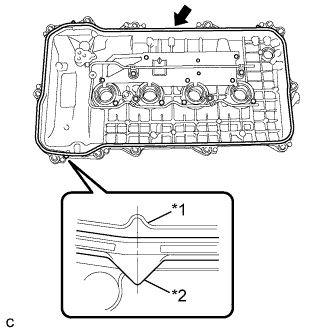 |
Install a new cylinder head cover gasket to the cylinder head cover.
| *1 | Cylinder Head Cover |
| *2 | Cylinder Head Cover Gasket |
| 44. INSTALL CYLINDER HEAD COVER SUB-ASSEMBLY |
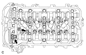 |
Install 2 new gaskets to the camshaft bearing cap.
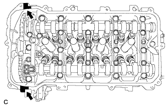 |
Apply seal packing as shown in the illustration.
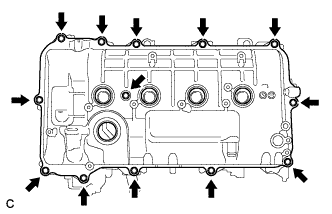 |
Install the cylinder head cover with a new seal washer and the 13 bolts.
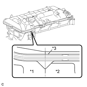 |
| *1 | Timing Chain Cover |
| *2 | Camshaft Housing |
| *3 | Cylinder Head Cover Gasket |
| 45. INSTALL ENGINE OIL PRESSURE SWITCH ASSEMBLY |
 |
Apply adhesive to 2 or 3 threads of the engine oil pressure switch assembly.
| *1 | Adhesive |
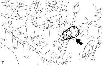 |
Using a 24 mm deep socket wrench, install the engine oil pressure switch assembly.
| 46. INSTALL ENGINE COOLANT TEMPERATURE SENSOR |
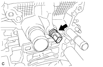 |
Install a new gasket and the engine coolant temperature sensor.
| 47. INSTALL KNOCK SENSOR |
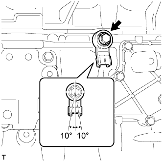 |
Install the knock sensor with the bolt.
| 48. INSTALL CRANKSHAFT POSITION SENSOR |
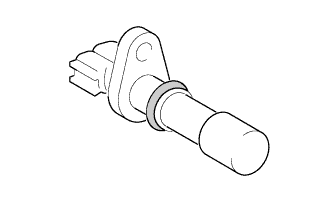 |
Apply a light coat of engine oil to the O-ring of the sensor.
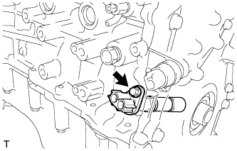 |
Install the crankshaft position sensor with the bolt.
| 49. INSTALL CAMSHAFT TIMING OIL CONTROL VALVE ASSEMBLY |
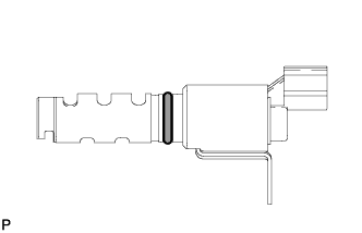 |
Apply a light coat of engine oil to a new O-ring and install it to the camshaft timing oil control valve.
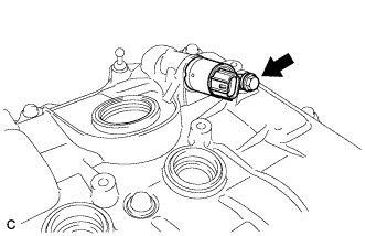 |
Install the camshaft timing oil control valve with the bolt.
| 50. INSTALL CAMSHAFT POSITION SENSOR |
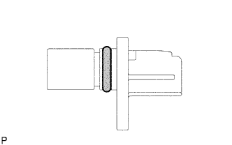 |
Apply a light coat of engine oil to the O-ring of the sensor.
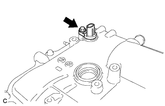 |
Install the camshaft position sensor with the bolt.
| 51. INSTALL SPARK PLUG |
Using a 14 mm spark plug wrench, install the 4 spark plugs.
| 52. INSTALL ENGINE COVER JOINT BOLT |
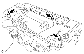 |
Install the 3 engine cover joint bolts.
| 53. INSTALL WIRING HARNESS CLAMP BRACKET |
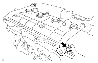 |
Install the wiring harness clamp bracket with the bolt.
| 54. INSTALL OIL FILLER CAP GASKET |
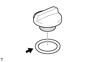 |
Install the gasket to the oil filler cap.
| 55. INSTALL OIL FILLER CAP SUB-ASSEMBLY |
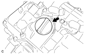 |
Install the oil filler cap.
