CYLINDER BLOCK > REASSEMBLY |
| 1. INSTALL STUD BOLT |
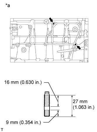 |
Using an E6 "TORX" socket, install the stud bolts as shown in the illustration.
| *a | LH Side |
| 2. INSTALL NO. 1 OIL NOZZLE SUB-ASSEMBLY |
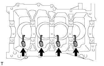 |
Using a 5 mm socket hexagon wrench, install the 4 oil nozzles with the 4 bolts.
| 3. INSTALL PISTON |
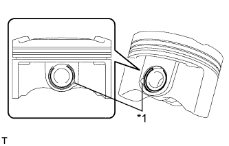 |
Using a screwdriver, install a new snap ring at one end of the piston pin hole.
| *1 | Service Hole |
Gradually heat the piston to approximately 80 to 90°C (176 to 194°F).
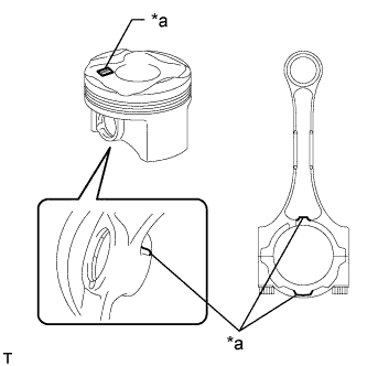 |
Align the front marks of the piston and connecting rod, insert the connecting rod into the piston, and then push in the piston pin with your thumb until the pin comes into contact with the snap ring.
| *a | Front Mark |
Using a screwdriver, install a new snap ring on the other end of the piston pin hole.
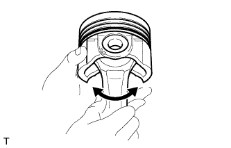 |
Check the fitting condition between the piston and piston pin by trying to move the piston back and forth on the piston pin.
| 4. INSTALL PISTON RING SET |
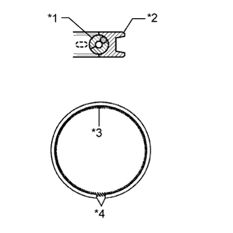 |
Install the oil ring expander and oil ring by hand.
| *1 | Oil Ring Expander |
| *2 | Oil Ring |
| *3 | Coil Joint |
| *4 | Oil Ring End |
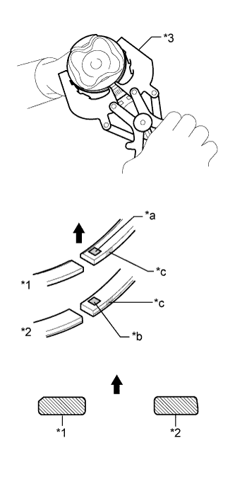 |
Using a piston ring expander, install the 2 compression rings so that the paint marks are positioned as shown in the illustration.
| *1 | No. 1 Compression Ring |
| *2 | No. 2 Compression Ring |
| *3 | Piston Ring Expander |
| *a | Code Mark (1R) |
| *b | Code Mark (2R) |
| *c | Paint Mark |
 | Upward |
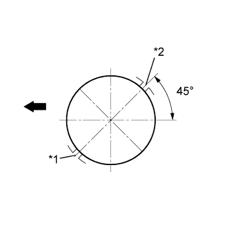 |
Position the piston rings so that the ring ends are as shown in the illustration.
| *1 | No. 1 Compression Ring and Oil Ring |
| *2 | No. 2 Compression Ring and Oil Ring Expander |
| Engine Front |
| 5. INSTALL CRANKSHAFT BEARING |
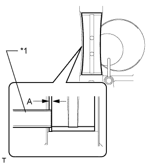 |
Install the upper bearing (except No. 3 journal).
| *1 | Vernier Caliper |
Install the upper bearing to the cylinder block.
Using a vernier caliper, measure the distance between the cylinder block edge and the upper bearing edge.
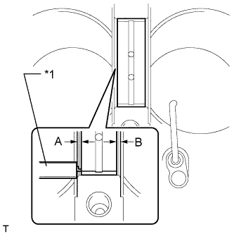 |
Install the upper bearing (for No. 3 journal).
| *1 | Vernier Caliper |
Install the upper bearing to the cylinder block.
Using a vernier caliper, measure the distance between the cylinder block edge and the upper bearing edge.
Install the lower bearing.
Install the upper bearing to the cylinder block.
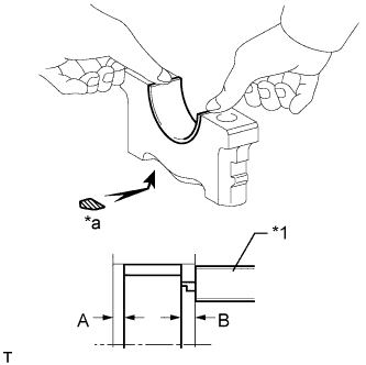 |
Using a vernier caliper, measure the distance between the bearing cap edge and the lower bearing edge.
| *1 | Vernier Caliper |
| *a | Mark 1, 2, 3, 4 or 5 |
| 6. INSTALL UPPER CRANKSHAFT THRUST WASHER |
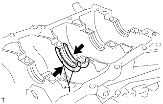 |
Install the 2 thrust washers to the No. 3 journal position of the cylinder block with the oil grooves facing outward.
| *1 | Oil Groove |
Apply engine oil to the crankshaft thrust washer.
| 7. INSTALL CRANKSHAFT |
Apply engine oil to the upper bearings and install the crankshaft to the cylinder block.
Apply engine oil to the lower bearings.
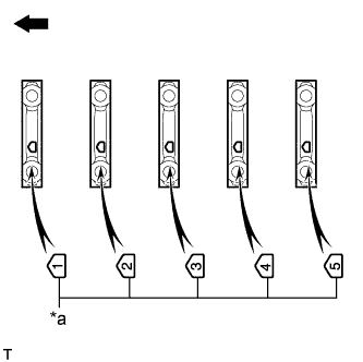 |
Examine the number marks and install the bearing caps to the cylinder block.
| *a | Number Mark |
| Engine Front |
Apply a light coat of engine oil to the threads and under the heads of the bearing cap bolts.
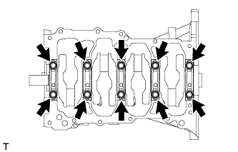 |
Temporarily install the 10 crankshaft bearing cap bolts.
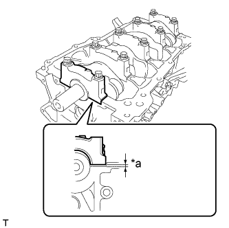 |
Push on the crankshaft bearing caps with your hand until the clearance between the crankshaft bearing caps and cylinder block is less than 5 mm (0.197 in.).
| *a | Less than 5 mm |
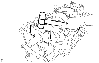 |
Using a plastic-faced hammer, lightly tap the bearing cap to ensure a proper fit.
Install the crankshaft bearing cap bolts.
Step 1:
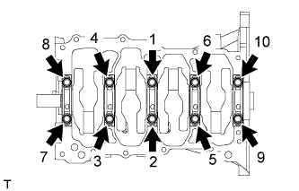 |
Install and uniformly tighten the 10 crankshaft bearing cap bolts in the sequence shown in the illustration.
Step 2:
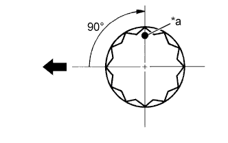 |
Mark the front of the bearing cap bolts with paint.
| *a | Paint Mark |
| Engine Front |
Tighten the bearing cap bolts 90° in the sequence shown in step 1.
Check that the paint marks are now at a 90° angle to the front.
Check that the crankshaft turns smoothly.
Check the crankshaft thrust clearance (Click here).
| 8. INSTALL CONNECTING ROD BEARING |
Install the connecting rod bearings to the connecting rods and connecting rod caps.
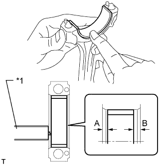 |
Using a vernier caliper, measure the distance between the edges of the connecting rods and connecting cap bearings, and the connecting rod caps and the connecting rod bearings.
| *1 | Vernier Caliper |
| 9. INSTALL PISTON SUB-ASSEMBLY WITH CONNECTING ROD |
|
Apply engine oil to the cylinder walls, pistons, and the surfaces of the connecting rod bearings.
| *1 | No. 1 Compression Ring and Oil Ring |
| *2 | No. 2 Compression Ring and Oil Ring Expander |
| Engine Front |
Position the piston rings so that the ring ends are as shown in the illustration.
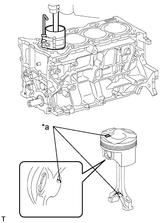 |
Using a piston ring compressor, push the correctly numbered piston and connecting rod assembly into the cylinder with the front mark of the piston facing forward.
| *a | Front Mark |
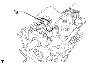 |
Check that the front mark of the connecting rod cap is facing in the correct direction.
| *a | Front Mark |
Apply a light coat of engine oil to the threads and under the heads of the connecting rod cap bolts.
Install the connecting rod cap bolts.
Step 1:
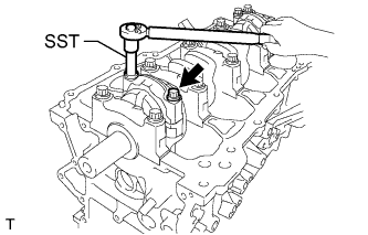 |
Using SST, install and alternately tighten the bolts of the connecting rod cap in several steps.
Step 2:
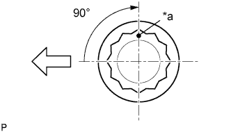 |
Mark the front of the connecting rod cap bolts with paint.
| *a | Paint Mark |
 | Engine Front |
Tighten the cap bolts 90° as shown in the illustration.
Check that the crankshaft turns smoothly.
Check the connecting rod thrust clearance (Click here).
| 10. INSTALL NO. 1 VENTILATION CASE |
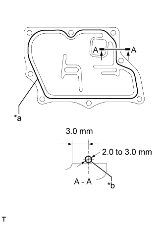 |
Apply seal packing in a continuous line as shown in the illustration.
| *a | Seal Packing |
| *b | Seal Packing Diameter |
| Seal Packing Diameter | Distance from inside edge of cover to center of seal packing |
| 2.0 to 3.0 mm (0.0787 to 0.118 in.) | 3.0 mm (0.118 in.) |
Type A:
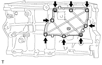 |
Install the ventilation case with the 6 bolts and 2 nuts.
Type B:
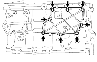 |
Install the ventilation case with the 8 bolts.
